Enginursday: Battery Management
This post explores how to use the power control features of the Battery Babysitter to make a product with the features we expect from portable embedded electronics.

In this modern age of cellphones, we've all come to expect a certain degree of elegance from our portable electronics' battery systems. But in DIY electronics it's common to find jumpers or switches that brutally disconnect the battery from its host. Or, no disconnect at all and puffy, discharged LiPos lying about haphazardly on the workbench. In my FLiR Pi Cam build, for instance, though voltage monitoring was built in, I left it to the user to isolate the batteries via a DPDT switch recessed in the body --- not very elegant at all!
This post explores how to use the power control features of the Battery Babysitter to make a product with the features we expect from portable embedded electronics.
The Host Project
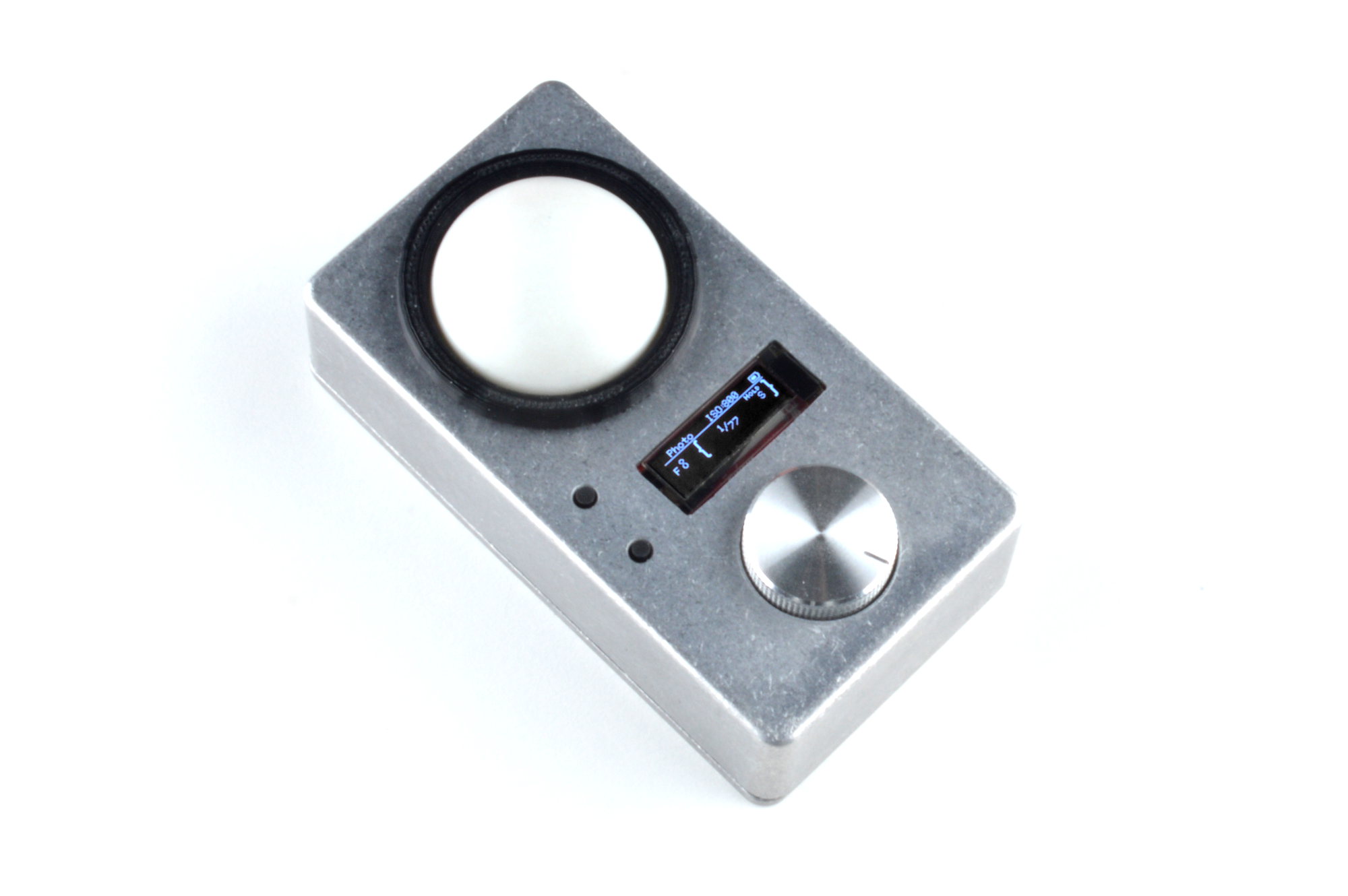
This is an incident light meter I built inspired from another DIY project I found at kadookacameraworks.com. I built it partly because I wanted to try some menu stuff out on the screen, and partly because I could use it to help light scenes for photography.
Incident light meters need to be thrown in a camera bag and used on and off during a shoot, often from odd angles. It just wouldn't make sense to have a wire that needed to be plugged in, so this is a great platform to try out the Battery Babysitter in order to make a product that performs as people expect.
The "actual" functions of the device are really just obtained by connecting the TSL2561 sensor to the I2C bus and whacking on a TeensyView, followed by coding, coding and more coding. And maybe a little math mixed in there. At the end I'll leave you with a schematic and repository, but this isn't about how light is measured; it's about batteries and usability. So let's get to it!
Design Goals
It's a good idea to specify what you want in the beginning when designing something. Here's what I came up with for adding battery support to my project.
- Low off-power requirements/no mechanical isolator. This thing should take months to discharge while off.
- Screen icons for battery:
- Must display quantity of "% use remaining"
- May display battery charging state.
- Minimize number of buttons.
- Sleep after some length of time (self power-down function).
Fulfilling Those Goals
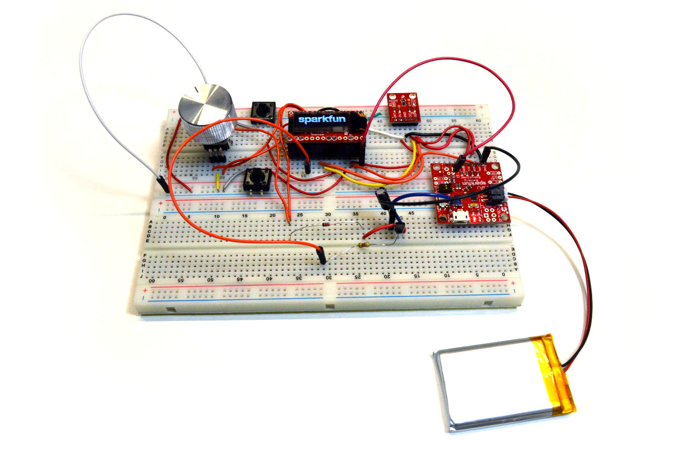
Before stuffing the project in the box, the entire project was developed on a breadboard. This allows the circuits in question to be tested and the construction to be well thought-out, avoiding sudden last-minute changes to the design after mechanical production has begun.
If we can describe how each goal is met, and how we can test each goal in the prototype, we can have confidence that the circuit will work as expected. So let's do that now.
Low Off Power
- The Battery Babysitter must be able to go into SYSOFF mode. We'll test this by measuring the off current through the battery terminal.
Pouring through the Battery Babysitter's schematic, power flow goes first through the fuel gauge IC, through the charger IC, then to the user. Looking for off currents in the respective datasheets,
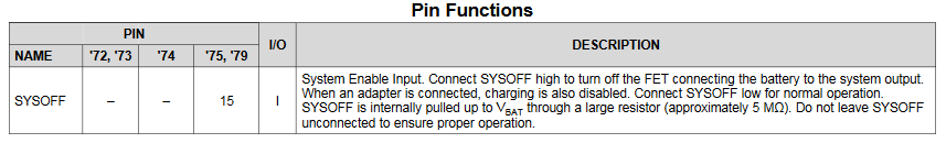
The charger is a bit cryptic in off current. The SYSOFF pin is pulled up with a 5 meg resistor, so the control load connected internally must be quite low, below 1uA. This is good, but the charger is downstream of the fuel gauge, so this pin alone can't turn everything off.
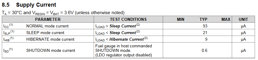
The fuel gauge specifies a few operational modes. For lowest operation, the device should be commanded to shut down by I2C.
Ideally, I expect less than 5uA of drain during off time, which would take years to drain a 1000mAh battery. In reality, I found that the process of shutting down the fuel gauge was quite involved, and it's intended to operate automatically. Conceding that design point, the measured battery off current came to about 60uA. At 1000mAh, that's almost two years of off time before the battery goes dead. I'll expect to charge this every couple months.
Screen Icons
- The screen must display a little battery in the corner and a symbol to show whether it's charging or not.
A bitmap image is used to mock up what the icons will look like
To make the graphics of the battery (and the screen in general), I used a bitmap editor extensively. Ok, you got me; I used mspaint with the zoom all the way in and the grid enabled. Then, I converted the pixels into HEX, knowing that the MSb is on top. For instance, the plug starts with 0x28, 0x28, 0x7C... The graphics are encoded into functions like drawPlug and batteryStyle1(x, y, %) so they can be easily used.
To detect charge state, it's easy to look for a positive current flow into the battery. If the condition is met, the plug is drawn. To prevent constant drawing on the screen, though, I check the current and percent remaining by the Babysitter's SOC (state of charge) function and only update if there is a new value to display.
Minimize Number of Buttons
- Reuse a function button for both the power supply enabler and the intended function. To test, the button must not interfere with the operation of the power supply while operating, and the digital input pin must still be able to detect changes in voltage while the power system is enabled.
The idea of the SYSOFF pin is that it floats high (through a 5meg resistor) and needs to be pulled low in order to get the Babysitter to come online. By connecting two sink paths to the pin, essentially a NOR gate is created.
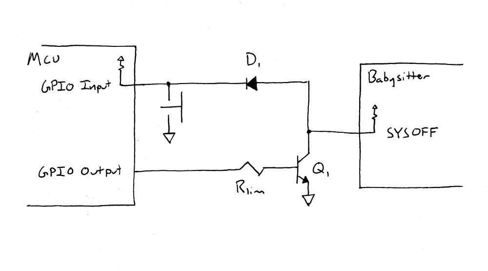
The first path is when the button is pressed, SYSOFF is pulled low through the diode. The second path occurs when the GPIO line is driven high, turning on the BJT to pull SYSOFF low.
The theory of operation is that when users want to use the system, they hold the power button until the processor boots. The first thing the processor does is configure its power control pin and pull SYSOFF low. Now the user can let go of the button, and the system remains on. When the system wants to shut itself down, it can release the power control line. The SYSOFF line goes high, and everyone goes to sleep.
The diode is included to allow the button to function normally on its input pin while the SYSOFF line is being held low by the processor.
Sleep After Some Length of Time
- The system must be able to turn itself off from firmware.
This can be done by bailing from the menu state machine if an mstick count has expired. Not yet implemented. For now, power off occurs when the soft key is hit in the system menu.
The Firmware
To make the system 'catch' as soon as possible, the power pin is configured and asserted as the first thing within begin().
void setup()
{
    //Assert power on pin
    pinMode(PIN_POWER_ON, OUTPUT);
    digitalWrite(PIN_POWER_ON, HIGH);

    //...
Then, when I want to turn the whole thing off, I simply drive the pin low in response to a button operation. There's a bit more here to show the user what the system is doing, and to provide an out if the system fails to shut down.
if( encButton.serviceRisingEdge() )
    {
        oled.clear(PAGE);
        oled.setFontType(1);
        oled.setCursor(6, 6);
        oled.print("Power down.");
        oled.display();
        delay(1000);
        digitalWrite(PIN_POWER_ON, LOW);
        delay(4000);
        oled.clear(PAGE);
        oled.setCursor(6, 6);
        oled.print("Failed!!!");
        oled.display();
        delay(1000);
        oled.setFontType(0);
        oled.clear(PAGE);
        oled.display();
        nextState = pSystemInit;
    }
As an example of graphics drawing, here's what the battery widget function does. First, it writes pixels to the screen memory with a bytewise draw command, and then it fills in the battery area based on the input percent.
void OLEDFunctions::batteryStyle1( uint8_t xIn, uint8_t yIn, float percent )
{
    drawByte(xIn + 0,yIn + 0,0xFE);
    drawByte(xIn + 1,yIn + 0,0x82);
    drawByte(xIn + 2,yIn + 0,0x82);
    drawByte(xIn + 3,yIn + 0,0x82);
    drawByte(xIn + 4,yIn + 0,0x82);
    drawByte(xIn + 5,yIn + 0,0x82);
    drawByte(xIn + 6,yIn + 0,0x82);
    drawByte(xIn + 7,yIn + 0,0x82);
    drawByte(xIn + 8,yIn + 0,0x82);
    drawByte(xIn + 9,yIn + 0,0xEE);
    drawByte(xIn + 10,yIn + 0,0x38);

    line(xIn + 2, yIn + 2, xIn + 2 + (percent * 6), yIn + 2);
    line(xIn + 2, yIn + 3, xIn + 2 + (percent * 6), yIn + 3);
    line(xIn + 2, yIn + 4, xIn + 2 + (percent * 6), yIn + 4);

};
All graphic functions in this project exist in a class that inherits the TeensyView object from the library. This separates the complicated drawing commands from the complicated state machine. The decoupling of these two things really helps to allow the firmware to be expanded --- for example, when a new menu screen needs to be created.
Project Files
Take a look at this schematic to see how everything is wired together. If you're interested in actually making this project, or just seeing how it works, the code, schematic and 3D printer models can be found in a GitHub repository.
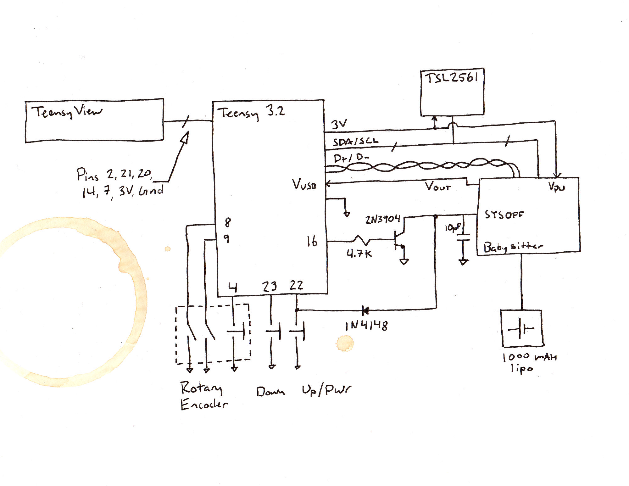
You can see that the Babysitter's output voltage drives the Teensy's bulk input (Vusb), which is regulated down to 3.3V for the Teensy and attached systems. Also, the USB communication lines have been extended to the convenient exposed PTH pads of the Babysitter, so the Teensy can be reprogrammed with the case closed.
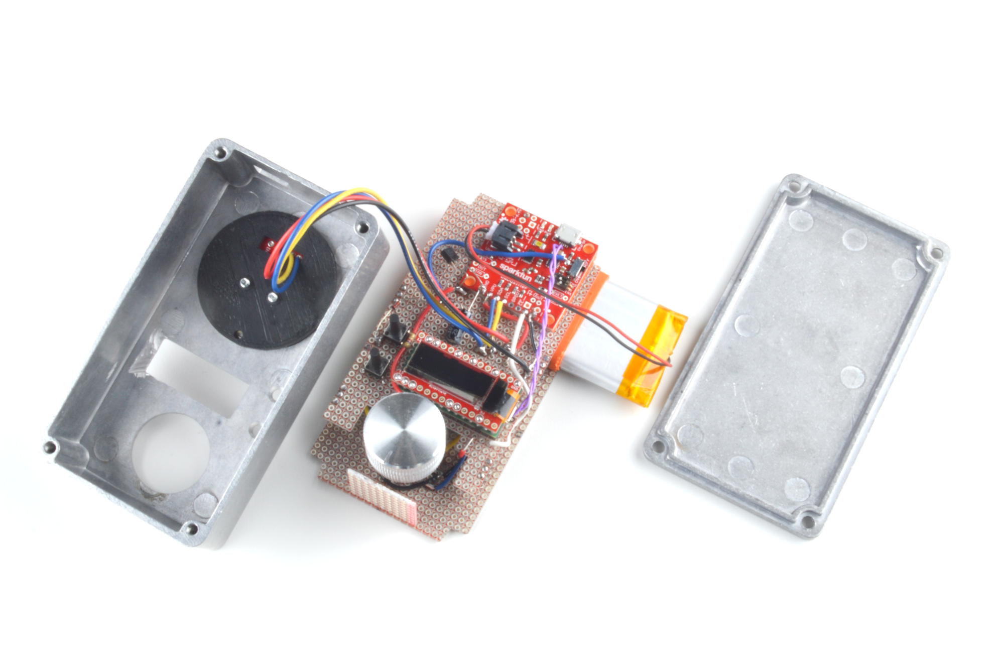
The mechanical build is designed so the battery slides between a couple of snappable proto boards, and the whole assembly slides into the enclosure. No case screws!
Parts used in this build:
- Teensy 3.2
- TeensyView
- TSL2561 Breakout
- Battery Babysitter
- 1000mAh LiPo
- Rotary Encoder
- Knob
- Tall Tack Switches (x2)
- Discrete Semiconductor Kit
- Resistors
- Capacitors
- 112x61x31mm Enclosure
- Snappable Breadboard (x2)
- Ping Pong Ball
And again, the repository can be found here:
Please share your thoughts and ideas in the comments below.
Happy making!
---Marshall


The Battery Babysitter must be able to go into SYSOFF mode. We’ll test this by measuring the off current through the battery terminal.
maybe you can give a picture on this
Nice. You remembered to put in the requisite coffee mug ring on your hand drawn schematic. Very classy. :-D
Thanks! But this is 2017 so it's actually a digital coffee ring that has white sent to transparency, which was overlaid on the original. ;)
" or the GIPO output can pull the line low to turn the system on." I see an NPN open collector driver, shouldn't the gate be driven high (via GPIO) to enable the transistor to drive the SYSOFF signal low? Or maybe that's what you meant and it's just the wording that threw me off.
Your analysis is correct! I was a bit high-level with that sentence though, and left out words! I'll go in and see if I want to reword the section a bit.
Maybe it should read: "The (processor) can pull the (SYSOFF) line low (by driving its GPIO high) to turn the system on."
Also, because we're talking about words and meaning, BJTs have a base, mosfets have a gate! ;)
Thanks for the comment!
LOL yes a base, you got me there!
To be honest, that one gets me too sometimes.
OK, I think I got it a little clearer in the post now.
While we are being pedantic, it isn't just MOSFETs that use the term "gate" for the controlling pin. AFAIK it's both MOSFETs and JFETs (though I haven't seen a JFET outside of class many solar orbits ago.) Also, don't most thyristors use "gate"?
Hmmm... I don't want to spend too much time here at work researching this, but do any of the other simple solid state devices other than the BJT use "base"?