- Home
- Product Categories
- Arduino Boards
- SparkFun Qwiic Micro - SAMD21 Development Board


SparkFun Qwiic Micro - SAMD21 Development Board
Looking for a super small microcontroller to use with the Qwiic eco-system? The SparkFun Qwiic Micro is molded to fit our standard 1"x1" Qwiic standard size which makes it one of our smallest micro-controller offerings to date. At it's core is the powerful and versatile ATSAMD21E18, which is an ARM Cortex M0+, 32-bit microcontroller, with 256KB of flash memory that can run at up to 48MHz! It has 12 digital pins which include 5 analog pins, SPI, I²C, and an additional UART data bus as well as a Qwiic connector for easy integration into the Qwiic ecosystem and I²C prototyping.
On the underside of the Qwiic Micro, we've left open pads for a LiPo Battery connector that you can add yourself, if you wish you can make the micro-controller portable. We've also provided pads on the underside for a flash memory chip to maximize the board's memory capacity. The SparkFun Qwiic Micro comes programmed with a UF2 Bootloader making it easy to program with easy driver installation! If you need a tiny but mighty micro-controller for you next project check out the SparkFun Qwiic Micro.
The SparkFun Qwiic Connect System is an ecosystem of I2C sensors, actuators, shields and cables that make prototyping faster and less prone to error. All Qwiic-enabled boards use a common 1mm pitch, 4-pin JST connector. This reduces the amount of required PCB space, and polarized connections mean you can’t hook it up wrong.
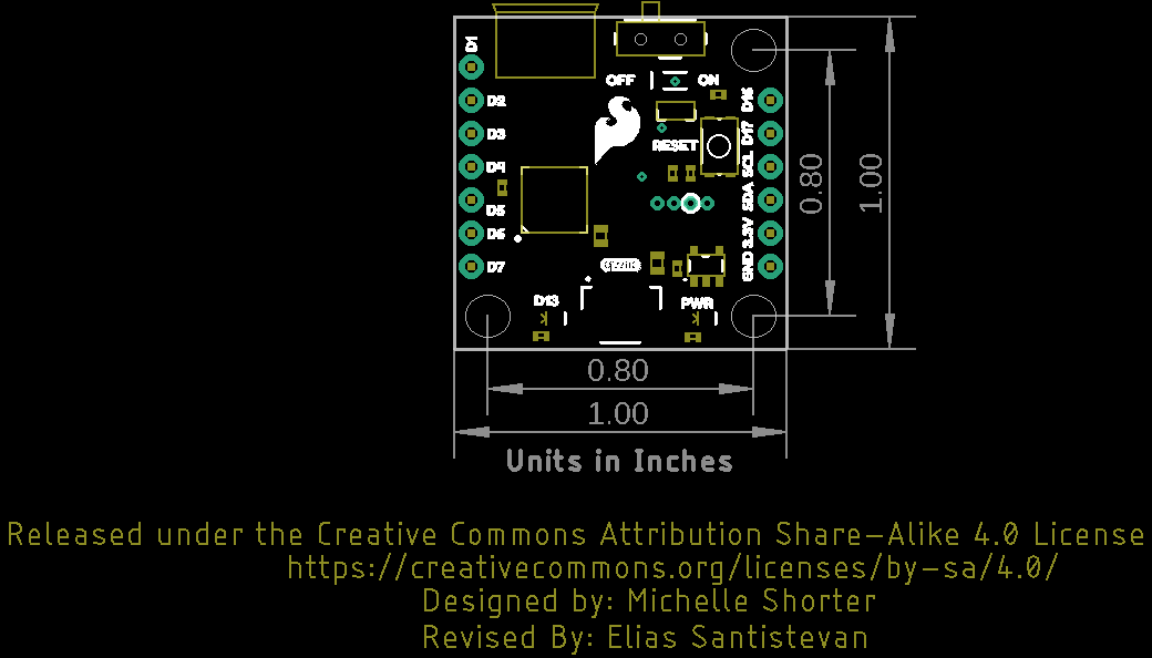
- Dimensions: 1in x 1in
- Optional LiPo Port
- Expandable Flash Memory
- Qwiic Connector
ATSAMD21E
- 48 MHz
- 256KB
- 32K SRAM
- UF2 Bootloader
SparkFun Qwiic Micro - SAMD21 Development Board Product Help and Resources
Qwiic Digital Indoor Thermometer
July 15, 2020
Qwiic-ly build a digital indoor thermometer to measure the ambient temperature of the room and display it using an OLED on an I2C bus!
Qwiic GPS Clock
September 14, 2020
What time is it? Time for you to... Qwiic-ly build a GPS clock and output it to a display! This project provides you with the current date and time using GPS satellites. Read the date and time as a digital or analog clock. Or even configure the clock for military, your time zone, or automatically adjust the time for daylight savings time!
Adding More SERCOM Ports for SAMD Boards
February 4, 2019
How to setup extra SPI, UART, and I2C serial ports on a SAMD-based boards.
SparkFun Qwiic Micro (SAMD21E) Hookup Guide
October 24, 2019
An introduction to the Qwiic Micro SAMD21E. Level up your Arduino-skills with the powerful SAMD21 ARM Cortex M0+ processor!
Core Skill: Programming
If a board needs code or communicates somehow, you're going to need to know how to program or interface with it. The programming skill is all about communication and code.
Skill Level: Rookie - You will need a better fundamental understand of what code is, and how it works. You will be using beginner-level software and development tools like Arduino. You will be dealing directly with code, but numerous examples and libraries are available. Sensors or shields will communicate with serial or TTL.
See all skill levels
Core Skill: Electrical Prototyping
If it requires power, you need to know how much, what all the pins do, and how to hook it up. You may need to reference datasheets, schematics, and know the ins and outs of electronics.
Skill Level: Rookie - You may be required to know a bit more about the component, such as orientation, or how to hook it up, in addition to power requirements. You will need to understand polarized components.
See all skill levels
Comments
Looking for answers to technical questions?
We welcome your comments and suggestions below. However, if you are looking for solutions to technical questions please see our Technical Assistance page.
Customer Reviews
4.6 out of 5
Based on 5 ratings:
1 of 1 found this helpful:
Huge power in a tiny format
Super powerful 24 bit processing at 48MHz in a square inch - brilliant for space restricted projects with demanding time constraints.
1 of 1 found this helpful:
Nice little board
I somehow overwrote the UF2 bootloader or otherwise rendered it inoperable when trying to write a bare-metal hex file -- I ended up writing my own bootloader to work over a 485-bus using the 4 pin swd header with a J-Link programmer (I didn't realize this chip didn't have a ROM based bootloader to fall back on). While making the bootloader I noticed that the documentation is a bit off in it's references to D16 and D17. The Graphical Datasheet shows D16 as TX and D17 as RX (the PA22 and PA23 port references are correct -- the TX and RX labels are reversed) and the Schematic shows PA22 as D16 (should be D17) and PA23 should be D16.
Great little board that could use some improvements
I've really enjoyed using the Qwiic Micro over the past couple of months. I love how small the form factor is and the ON/OFF switch definitely comes in super handy for projects.
That being said, there have been some negatives for me using this board. I never expected not having VBAT broken out would bother me as much, but gosh is it an inconvenience! Measuring the battery voltage is virtually impossible if you solder on the JST battery connector. I realize there's not a lot of real-estate available, but IMHO one of the mounting holes could be sacrificed to make way for VBAT pin.
Measuring the battery voltage through an onboard voltage divider (e.g. 1MΩ/1MΩ + 0.1 uF capacitor) would be a dream come true!
SAMD memory is nice but...
SAMD memory is nice but...I want to drive a micro servo, as I do with my Pro Micro, but there is no RAW 5V brought out to a pin. Otherwise, very compact, works well.
This is a clever device
I examined it shortly after it arrived. It is safe to say that this is the best thing to happen to the Qwiic community since first announcements.
Right now it is on my schedule "to do something" with it.
Well, that's a spiffy little board. I'm excited to see it!
Shout out to you for this excellent idea
It's finally live! =P
From my experience (and according to one review, I'm not alone), the silkscreen and hookup guide incorrectly state that the Serial pins are TX/RX = 16/17. On my board it is TX/RX = 17/16.
This is a great board. Only the necessary for small qwiik based projects - when you are not in the mood for soldering.
However, the mcu always boot into bootloader when powered (even though it's not connected to a computer). This means I always have to push the reset button to actually initiate the firmware I write. Could this be fixed somehow, f.ex. such that the default state is to boot into the firmware instead of the bootloader?
This is probably a dumb question but it’s not clear to me, can this be programmed like Arduino?
Yup! It sure can.
The Qwiic Micro was added to the SparkFun SAMD board definitions a few days ago, which appear to be available in the Arduino IDE Boards Manager (v1.7.0).
Does it have a lipo charging circuit built in?
I think the next Qwiiic board should be a lipo charger circuit with a battery monitor and fuel gauge. Kind of like a Qwiic version of the Battery babysitter.
yes please! although I do prefer microcontrollers with LiPo connector AND charger built in.
To keep the board size to a minimum, there is no LiPo charger IC built-in.
If you managed to fit one on the board, this would easily be an insta-buy :)