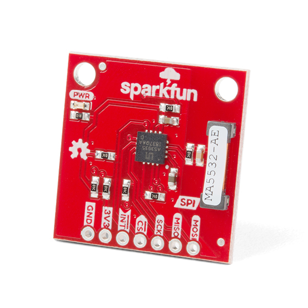
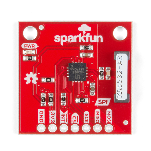
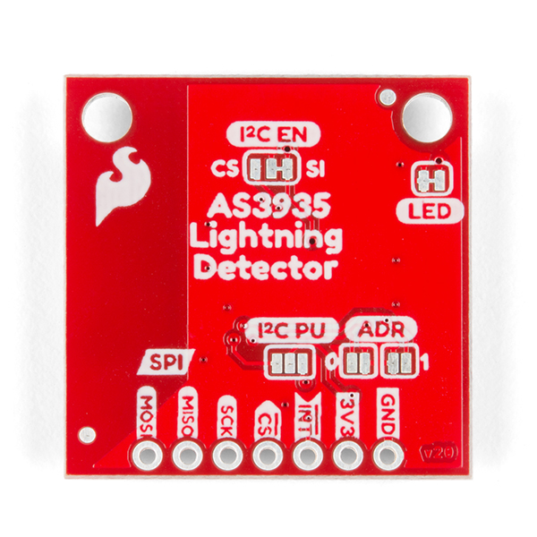
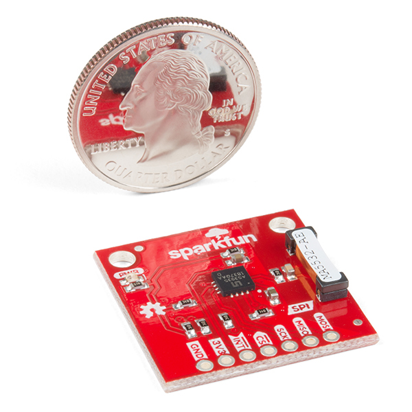
SparkFun Lightning Detector - AS3935
The SparkFun Lightning Detector adds lightning detection to your next weather station to make sure you are aware of any potential hazardous weather heading your way. The AS3935 is capable of detecting lightning up to 40km away with an accuracy of 1km to the storm front with a sensitive antenna tuned to pick up lightning events in the 500kHz band.
There are a number of sources that can cause false positives but the lightning detector itself can reliably filter these out by default. If not, we've made sure to include settings you can configure using the lightning detector library to increase the chip's robustness to noise and false positives. The lightning detector library also gives you access to settings such as storm sensing sensitivity when detecting indoors vs outdoors, or the number of lightning strikes needed to trigger an interrupt.
- Lightning Sensing
- 40km Range with accuracy of 1km in 14 steps
- Features
- Programmable Detection Levels
- Distance to storm estimation
- "Disturber" (false event) rejection algorithm
- Indoor and Outdoor Settings
- SPI Interface
- Operating Range
- Supply Voltage: 2.4V - 5.5V
SparkFun Lightning Detector - AS3935 Product Help and Resources
SparkFun AS3935 Lightning Detector Hookup Guide (v20)
July 25, 2019
Are you worried about the looming clouds in the distance, how far away is that storm exactly? Add lightning detection with the AS3935 to your next weather station or your next bike ride!
Core Skill: Soldering
This skill defines how difficult the soldering is on a particular product. It might be a couple simple solder joints, or require special reflow tools.
Skill Level: Noob - Some basic soldering is required, but it is limited to a just a few pins, basic through-hole soldering, and couple (if any) polarized components. A basic soldering iron is all you should need.
See all skill levels
Core Skill: Programming
If a board needs code or communicates somehow, you're going to need to know how to program or interface with it. The programming skill is all about communication and code.
Skill Level: Rookie - You will need a better fundamental understand of what code is, and how it works. You will be using beginner-level software and development tools like Arduino. You will be dealing directly with code, but numerous examples and libraries are available. Sensors or shields will communicate with serial or TTL.
See all skill levels
Core Skill: Electrical Prototyping
If it requires power, you need to know how much, what all the pins do, and how to hook it up. You may need to reference datasheets, schematics, and know the ins and outs of electronics.
Skill Level: Rookie - You may be required to know a bit more about the component, such as orientation, or how to hook it up, in addition to power requirements. You will need to understand polarized components.
See all skill levels
Comments
Looking for answers to technical questions?
We welcome your comments and suggestions below. However, if you are looking for solutions to technical questions please see our Technical Assistance page.
Customer Reviews
3.3 out of 5
Based on 3 ratings:
1 of 1 found this helpful:
Very buggy
Got this running on an ESP32 no problem. I used a variation of the Example2 SPI set to INSIDE. I noticed a lot of disturbers even with the disturber mask set to true. Looked at the library and it looks like the command maskDisturber() returns without doing anything. After trying a lot of values for noiseFloor, watchDog, and spike, there wasn't much effect. Then I found the example has the line lightning.resetSettings() uncommented so I'm guessing that reset the tuningCap value too. So, I ran Example3 to set the cap value and no matter what multiple of 8 is entered i.e. lightning.tuneCap(64), the value read back is always 0 and the frequency found on the IRQ line never changes. Very frustrating.
2 of 3 found this helpful:
Use a 2 meter USB cord and move it away from your computer
Edit: I installed a 2 meter USB cord and my issues with the Lightning Detector disappeared. I now get full range and efficiency and it does what the spec sheet says, via SPI. I upgraded my review to 4 stars.
Sparkfun has superior technical support for this product. The example software along with online documentation make it a snap to get it working and start learning about its features with an Arduino Uno. Non-Sparkfun third party support includes software and guides to work with Parallax Propeller P8X32A and Raspberry Pi. None are more helpful than Sparkfun.
My setup is Indoor and the factory SDR setting came in at exactly 500kHz.
So far I have tried more than 15 combinations of adjustments for Noise, Disturber, Watchdog, Spike and Lightning Threshold. I started with the default settings and gradually increased the settings one-by-one up to maximum. Each increased setting shortens detection distance.
The AS3935 sends many overhead lightning strike alerts when there is no lightning and when storms are many miles away. I get no Noise alerts and I ignore Disturber events.
Unfortunately, the AS3935 Lightning Detector is not fit for its intended use for me.
1 of 3 found this helpful:
First Impression
Have tried it for a few days only. So far even in the presence of local visible lightning it is far less sensitive than I expected. SDR at 500 kHz sees lots of strikes but this module only reports occasional disturbance with no distance. Tried two sensitivity settings. Tuned within .6% of 500. Maybe I'm not using or mounting it well. Don't know what's wrong.


I found it difficult to debug this part since you seldom have lightning around when you need it. I designed a simple lightning signal generator that creates the pattern the AS3935 is looking for: Details are on this webpage: https://sites.google.com/view/as3935workbook/home
Fantastic write up! Thanks for posting.
Sweeeeet. =)
Has anyone installed this device in close proximity (like in the same case) with an Arduino or recent Raspberry Pi? Is it subject to interference from the CPU it is attached to?
I'd like to stuff this device and a RPi Zero W in the same enclosure. My old Pi B is a pretty powerful RFI generator between 470 and 510kHz, although it does have some unshielded peripherals hanging off it, and I2C is enabled. Suprisingly the signals at 1000 and 1500 kHz are not very strong.
I'm actually thinking of using this unit to view disrupters and noise as a proxy for home power line quality, since lightning rarely occurs in my area. I assume I'll to need to move the device to another part of the house to escape the intense RFI from the Pi and other computers in my lab.
I tried the board in SPI mode. The SPI software reported a ready condition, even when the board was NOT installed in the circuit!!
I cut the trace on the board and bridged CS to ground, per the text. Hooked it up in I2C mode. The I2C software reports the board as ready correctly. So much for the more "reliable" SPI mode of operation.
I am now building the lightning simulator as described here, https://sites.google.com/view/as3935workbook/home, for future testing, with the board in I2C mode.
Just put in an issue in the GitHub registry. The library doesn't work on certain MCU's, like SparkFun Pro nRF52840 - getting the dreaded:
~Arduino/libraries/SparkFun_AS3935_Lightning_Detector_Arduino_Library/src/SparkFun_AS3935.cpp: In member function 'bool SparkFun_AS3935::beginSPI(uint8_t, uint32_t, arduino::SPIClass&)':
~SparkFun_AS3935_Lightning_Detector_Arduino_Library/src/SparkFun_AS3935.cpp:58:9: error: 'class arduino::MbedSPI' has no member named 'setBitOrder' SPI.setBitOrder(MSBFIRST); ^~~~~~~~~~~ exit status 1 Error compiling for board Arduino Nano 33 BLE.
Hopefully, this will get rectified. Using it on a SAMD based board and it is fantastic.
Thanks for the heads up.
I am sure the engineer for this product will be taking a look into the issue, but I believe your error messages have to do with the compatibility with SPI library for the respective Arduino cores. I know the Mbed port for the Arduino Nano 33 BLE is relatively complex, but I am sure we will do what we can to resolve the issue.
Is anyone else having issues seeing images in the tutorial?
Thanks for saying something! We had some issues with our servers and lost a few images but it wasn't clear which ones were lost. I'll get those updated as soon as possible.
All but one have been fixed - the last remaining image should be fixed today.
I just received two of these units and got them running. I checked the antenna tuning and they seem to be running right at 500 kHz. We just had a lightning storm roll over our place but all I got were disturbers with over 100 incidents.
I trying the example code with this heading: By: Elias Santistevan SparkFun Electronics Date: July, 2019 License: This code is public domain but you buy me a beer if you use this and we meet someday (Beerware license). Example 2 These are the settings that come up when I boot: 18:16:34.781 -> AS3935 Franklin Lightning Detector 18:16:34.781 -> Schmow-ZoW, Lightning Detector Ready! 18:16:34.781 -> 18:16:34.781 -> Are disturbers being masked: YES 18:16:34.781 -> Are we set for indoor or outdoor: Indoor. 18:16:34.781 -> Noise Level is set at: 2 18:16:34.781 -> Watchdog Threshold is set to: 2 18:16:34.781 -> Spike Rejection is set to: 2 18:16:34.816 -> The number of strikes before interrupt is triggerd: 1 18:16:35.125 -> Disturber.
That is odd. This is a question better suited to our forums: forums.sparkfun.com. However, I do have a suggestion: try changing your setting to OUTDOOR to see if you have better results. Clearly it's detecting lightning but is not registering it as lightning which leads me to suspect that the INDOOR setting may be too robust in your case.
I purchased a very similar breakout board from a different vendors years ago. I am trying to protect a fairly significant investment in computer gear by power it all down and disconnecting from power when a storm comes by. I found this chip (not the break out board implementation) to be much less than satisfactory. First if the detector is keep inside, every time some motor kicks on in the house (AC units, furnace blower, dishwasher, disposal, ...) I would get a false alarm. If I reduced the sensitivity (via registers) then I would miss storms. I never did try this outdoors away from the house because of the difficulty in getting power to it.
The second problem is again with the chip (not the breakout board). They provide an "interrupt" pin to tell you of events. The problem is that when the interrupt pin is asserted, the interrupt service register (tells you why you got the interrupt) can't be read right away. You have to wait an ungodly amount of time before it becomes valid. If memory served me right something like a few milliseconds. Makes having an interrupt pin pretty idiotic. When the interrupt happens, you need to kick off a timer in you interrupt service routine. When that timer expires, then you can read the service register. Why you could not have held off the interrupt till the register was valid is beyond me. It is a huge bone headed error.
After several months of screwing around with the chip, it went into the junk drawer and I built a much more reliable detector from an old AM radio.
Again, I am sure the Sparkfun board is just fine (although I have not purchased one). It is the chip itself that has the issues.
The datasheet gives a nice tip about a way of reducing false triggers: "In consumer weather stations power can be saved and false triggers avoided by powering down the AS3935 based on humidity and pressure information." - Page 36 of v1.04 datasheet.
About the interrupt routine: it's documented in the datasheet that a wait of 2 ms is required before reading the relevant part of the register. "Whenever events happen, the AS3935 pulls the IRQ high and displays the interrupt in the REG0x03[3:0]. Figure 44 shows the interrupt register. After the signal IRQ goes high the external unit should wait 2ms before reading the interrupt register. The interrupt bus IRQ is set back to low whenever the interrupt register is read out." - Page 34 of v1.04 datasheet.
I did not mean to indicate that chip did not document the issue with the delay. Even the datasheet from 5 years ago had this documented. What I found aggrevating was having to wait the 2ms before getting to read the in service register. Of all the chips I have used in 25 years of electronic design, this is the first time I have seen an interrupt pin requires a delay before reading the ISR. In my opinion it is a terrible design. Yes, you can work around it.Just make sure you do not wait the 2ms in the interrupt service routine. You need to set a flag or a timer in the ISR and check it in the main loop. This "feature" made it tough to use in a very limited resource micro like an MSP430.
I am glad to hear the Sparkfun's library accounts for this issue.
Interesting that they recommend gating the events with other sensors. That I think must be new in the datasheet. I did not see that in the original version.
That is correct! The Arduino Library that we've written for this already accounts for this delay and is included in the "readInterrupt" function. There's no need to add your own 2ms delay. This is just an FYI for anyone using the library.
Thanks for the heads up, I'll let our TS team know about this quirk in case any other customers run into this issue.
This is awesome... I was going to build something like this using analog components. I've got a couple of questions: your example shows using it with a SparkFun Arduino clone, but it looks like it would work fine with a genuine Arduino Uno R3. Is that correct? I want it to be directional (for photography). Would it be possible to either shield it to provide directionality, or attach a home-made antenna that would do the same? Thanks!
That is correct, our clone is functionally comparable to the Arduino Uno, and so you're Uno would work just fine. Unfortunately, you could not get directionality with a single lightning detector. To your first question, a shield would only hinder the ability of the Lightning Detector to detect lightning. As to your second question, the antenna on the Lightning Detector and its' passive components were chosen so that they resonate at a specific frequency: 500kHz. In addition the components give the antenna a specific "Q-factor" or quality factor. This is also vital to its' ability to detect lightning. I have wondered if it would be possible to get direction with triangulation but I'm not familiar enough with the specifics of triangulation. Sorry about that, hopefully you can still find a way to integrate it into a project!
Can this be used to trigger a camera to take a photo of the lightning?
A photographer I know uses an AM transistor radio to trigger their camera. The radio audio amp might even be strong enough to drive a small relay.
It does have a trigger (an "interrupt") to do such a thing, however my gut is telling me "no". The time for the signal from the lightning has to travel to the Lightning Detector's antenna, then the Lightning Detector has to determine if it sensed lightning (which takes 2 milliseconds), and then the camera has to be alerted and then take a picture. All of that BEFORE the lightning strike disappears.
It could be tricky with the timing for a photo but you could possibly use a Raspberry Pi with a USB webcam. There was a project that I recently saw that "films the past" using a Pi and a USB camera. Basically the camera is constantly on and saves the last 7 seconds of video when the button is pressed. I would think the resolution and focus for the photo would be pretty bad when using a USB webcam as opposed to a DSLR though.
I'm sure there are similar projects, but check out the CameraAxe Arduino based camera controller. If I buy one of these my plan is to interface it with an older CameraAxe that I built. They provide a lightning sensor, but it's just a light sensor that detects the preliminary flash and fires the camera to capture subsequent flashes. I've wanted to experiment with something like this because I think the static RF interference precedes the initial flash and could trigger the camera. After that it would be a matter of determining the length of exposure to capture the entire event. Keep in mind, this is speculation on my part as I haven't tested the build yet.