- Home
- Product Categories
- Arduino Boards
- SparkFun Qwiic Pro Micro - USB-C (ATmega32U4)

SparkFun Qwiic Pro Micro - USB-C (ATmega32U4)
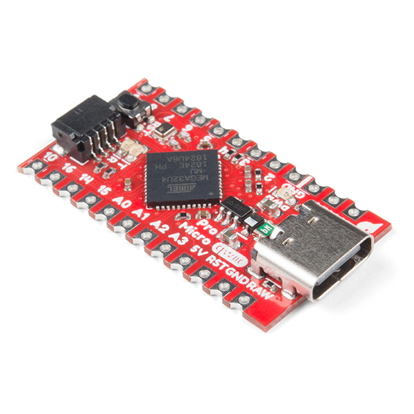
Here at SparkFun, we refuse to leave 'good enough' alone. That's why we're adding to our line-up of Arduino-compatible microcontrollers once more! The SparkFun Qwiic Pro Micro is a revision of the original Pro Micro and is, overall, functionally the same as the previous version. The board is the same size as the original Pro Micro but we added a few additional features by shrinking down some components on the board such as a reset button, Qwiic connector, USB-C, and castellated pads (this makes it really handy for you custom keyboard creators out there)! Think the Pro Mini except with an ATmega32U4 on board and full USB functionality.
This tiny little board does all of the neat-o Arduino tricks that you're familiar with: nine channels of 10-bit ADC, five PWM pins, 12 DIOs as well as hardware serial connections Rx and Tx. Running at 5V and 16MHz, this board will remind you a lot of your other favorite Arduino-compatible boards but this little guy can go just about anywhere. There is a voltage regulator on board so it can accept voltage up to 6VDC. If you're supplying unregulated power to the board, be sure to connect to the "RAW" pin on not VCC.
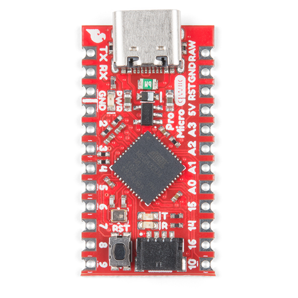
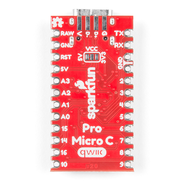
The benefit of the reset button is to quickly reset the board or place it into bootloader mode without the need to take out a piece of jumper wire. The USB micro-b connector has been replaced with the USB type C connector. The through-hole pads have castellated edges for each pin to add a lower profile in your projects should you decide to build it into another assembly during production. Finally, a Qwiic connector is populated on the bottom of the board to easily add Qwiic enabled I2C devices to your projects!
Not sure which Arduino or Arduino-compatible board is right for you? Check out our Arduino Comparison Guide!
The SparkFun Qwiic Connect System is an ecosystem of I2C sensors, actuators, shields and cables that make prototyping faster and less prone to error. All Qwiic-enabled boards use a common 1mm pitch, 4-pin JST connector. This reduces the amount of required PCB space, and polarized connections mean you can’t hook it up wrong.
- ATmega32U4 running at 5V/16MHz
- AP2112 3.3V Voltage Regulator
- Supported under Arduino IDE v1.0.1+
- On-Board USB-C connector for programming
- PTH Pads w/ Castellated Edges
- 9x 10-bit ADC pins
- 12x Digital I/Os (5 are PWM capable)
- Hardware Serial Connections
- UART (i.e. Rx and Tx)
- Qwiic Connector for I2C
- SPI
- Small Arduino-Compatible Board
- Reset Button
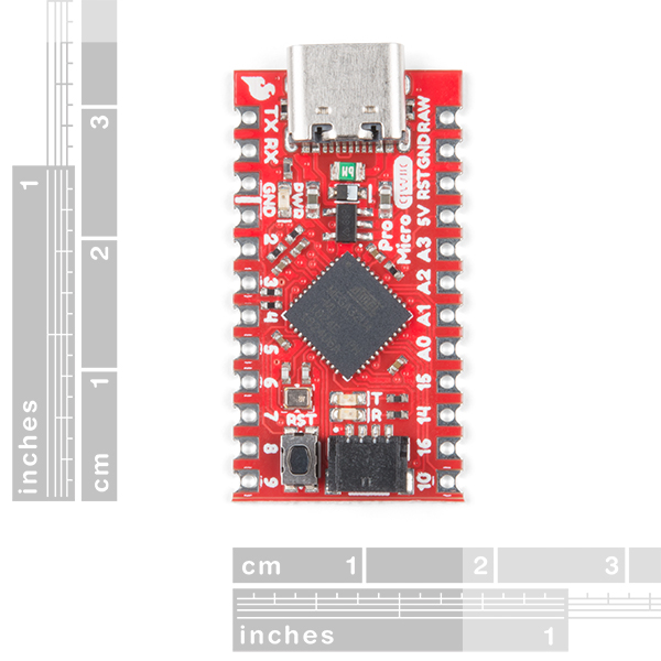
- Dimensions: 1.3in x 0.7in
SparkFun Qwiic Pro Micro - USB-C (ATmega32U4) Product Help and Resources
Qwiic Pro Micro USB-C (ATmega32U4) Hookup Guide
February 6, 2020
An overview of the ATmega32U4-based Qwiic Pro Micro USB-C, how to install it, and how to use it with Arduino.
Core Skill: Soldering
This skill defines how difficult the soldering is on a particular product. It might be a couple simple solder joints, or require special reflow tools.
Skill Level: Noob - Some basic soldering is required, but it is limited to a just a few pins, basic through-hole soldering, and couple (if any) polarized components. A basic soldering iron is all you should need.
See all skill levels
Core Skill: Programming
If a board needs code or communicates somehow, you're going to need to know how to program or interface with it. The programming skill is all about communication and code.
Skill Level: Rookie - You will need a better fundamental understand of what code is, and how it works. You will be using beginner-level software and development tools like Arduino. You will be dealing directly with code, but numerous examples and libraries are available. Sensors or shields will communicate with serial or TTL.
See all skill levels
Core Skill: Electrical Prototyping
If it requires power, you need to know how much, what all the pins do, and how to hook it up. You may need to reference datasheets, schematics, and know the ins and outs of electronics.
Skill Level: Rookie - You may be required to know a bit more about the component, such as orientation, or how to hook it up, in addition to power requirements. You will need to understand polarized components.
See all skill levels
Comments
Looking for answers to technical questions?
We welcome your comments and suggestions below. However, if you are looking for solutions to technical questions please see our Technical Assistance page.
Customer Reviews
4 out of 5
Based on 10 ratings:
1 of 1 found this helpful:
A joy to work with.
The documentation on this, and the USB-C functionality is fantastic.
I'm giving this a 4 star review because one of the solder pads came off during assembly (thankfully I could use the other side).
Overall I would highly recommend this, and I am looking forward to using these more in the future 🙂
Really awesome!
Easy to use, and worked flawlessly out of the box. Used it to create my own keyboard type of interface, and it connects to any computer easily and works as a HID. Would recommend 100%
One of my favorite little boards
This is pretty much everything I could ask for: USB-C, Qwiic, onboard reset button, and the 32U4 processor is a capable little chip with handy USB capabilities. The only thing is that at $20, it’s over 8 times as much as cheap Arduino Nano/Mini/Micro clones that I’m sure everyone is familiar with. I realize that it is a higher quality board designed and built by Sparkfun, but it really seems like $10-12 would be a lot more reasonable. If you compare it to the new RP2040 based board that is very similar to this one (DEV-17717) yet priced at $9.95, you’ll see what I mean. The RP2040 chip is MUCH more powerful than the ATmega32U4 and it appears to have more components on the board with it as well, such as external flash.
Worked great for keyboard build
This was used in a lily58 pro keyboard build as an upgrade for a different brand I was using.
The only thing that took me a while to figure out was that I had to click the RST button twice to program. If I only read the documentation first, much time could have been saved.
great for i2c projects
i use the 32u4 for USB-to-i2c HID projects, and the qwiic pro micro is a perfect uC for those projects. it's tiny, simple, and inexpensive, works fine with arduino 1.x and 2.0. would recommend.
Loving the footprint
Purchased this device as a daughter board. Once I got it to accept the (Arduino) program, it's all I envisioned for the project.
Need digital artifacts
Please create the footprint, 3D model (STEP file), and symbol for this module.
Very nice board
I purchased this board as my first Qwiic compatible board, and I am very pleased with it. I had some issues soldering the headers, and wish that there was a version with pre-attached headers. The board is responsive, and the Sparkfun Board tool worked well. Thanks Sparkfun!
Does not connect with USB 3 on a Windows computer
This will not be seen by a Windows computer with a USB 3 port. Sparkfun says this, but only buried in fine print on the hookup page.
Nice board - I will definitely be picking up a few for embedding into other projects!
One bit of feedback: I don't see level shifters on the Qwiic port, which is fine for I2C since that is an open drain arrangement and VIL, VIH, and VOL are all suitable for 3.3V devices.
However, a programming error could configure PD0 or PD1 as outputs driven high. In that case, the voltage on the Qwiic SDA/SCL lines would go up to near Vcc. The spec sheet says VOH is ≥ 4.2V @10mA if Vcc is 5V, and presumably it would go ≥ 5.2V if you run Vcc all the way to the limit.
It is worth documenting this assumption, since a programming error could cause the Qwiic bus to go out-of-spec and potentially damage sensitive I2C devices.
if you set the solder-jumper to 3.3V operation the ATMEGA 32U4 still runs on 16MHz ? According to the Datasheet the max. allowed clock-frequency for 3.3V operation is 8MHz
Yep. We're overclocking it (out of spec) at 16MHz/3.3V. We've done this on a few thousand units and haven't seen issues but your mileage may vary.
Please Break out PF1(ADC1) and PF0(ADC0) to pads on the board surface! They have functions like differential ADC that are not on any other pins.
Good feedback! Thanks! Agreed. We'll try to get those out on a future rev.
I think the hookup guide is misleading. I changed the jumper to 3.3V. It tells you to select 3.3V 8Mhz micro pro in the Arduino IDE. But that bricked my board. Also my reset button wasn't working outta the box. I couldn't figure out why the reset trick wasn't resetting the processor. I manually jumpered the reset and that worked but couldn't get it to hit bootloader mode correctly still. Then I ran the BAT file the instructions point you to but that never worked either. I finally cleaned the reset button and it started working again. Then I could do the double click and recover the board. I changed the setting back to 5V 16Mhz and the sketch loads and runs fine now. Very frustrating process to get through. Hopefully this helps someone else.
How are people mounting these? Adhesive velcro? Glue?
Are the CAD files ever going to get updated? I want a 3D model of this board to integrate into a project I'm working on and was just going to generate one from the EAGLE CAD, but it looks like the files in the USBC branch are still for the old Micro-B variant of the pro micro and haven't been updated for nearly a year. The commit history looks like there was attempts to update the files, but I assume they were just incorrectly committed?
EDIT: nvm, didn't realize the USBC branch wasn't the main branch, is there a reason master is kept out of date?
The CAD files are probably not going to be updated anytime soon as other projects and products have our burning attention.
Good eyes wrt USBC branch. For this product, it got a bit messy. The Pro Micro C 'revision' turned out the be very popular with the original maintaining is popularity. We are trying to maintain master for folks that still have or want to purchase the microB connector version.
Note: I have found that connecting the ProMicro to a USB 3.0 port will often, if not always, brick the board. The setup guide provides info on how to de-brick the board, but it's not a trivial task. I recommend always using USB 2.0.
I had a similar issue with the board, which I ultimately fixed. Out of the box, USB wasn't working at all, but I hooked up an AVR programmer and could get the blink program running. Still, none of the USB-related sketches would run and the serial port never showed up. Due to the nature of the USB 3 connector I couldn't test it directly, but I did hook up a microUSB board to the pads under the board. Same issue though, error logs complaining about enumeration errors. Spent an hour digging through forums to find that the 5.1k resistors were almost certainly the problem, and that this design is bad. Very, very carefully shorted them (what are they, 0402?) with wire, as suggested, fired it up, and everything worked fine. Would have preferred to replace them with 22 ohm resistors but I already spent so much time just getting this board into the state it's supposed to be in from SFE, I just didn't want to deal with it anymore.
The one thing i find disappointing is the lack of PC7 being broken out. Would have made my life a bit easier at using Timer4 to it's fullest, oh well. time to learn how to work with the invert !OC4A pin and implement a work-around. Shouldn't be hard. Luckily i don't need those PWM pins in sync. Though may have to keep in mind in future. Timer4 really is the reason i want to use the ATmega32u4 as it can take its clock of the PLL used to generate 96Mhz for USB. Allowing for the kind of PWM frequency normally only seen on 96mhz ARM controllers!
BTW: Have you guys ever noticed the Typo in the graphical datasheets? For years OC4A is on it as OCA4.
I think if you submit a "request" through the issues tab in the GitHub repository and state your case... that might be a more visible platform for the engineers to take into consideration, if we have a revision of the board. That being said, there are a limited number of pins that can be broken out for such a small form factor, so I think it was a trade off the engineer had to make.
Does anyone know what boot loader this uses?
Bricked two of these trying get the drivers right. The information was there I just misapplied it. Got it right on the third try. Tried the de-bricking procedures in docs with no luck.
Hey there. It looks like we found your forum post. We will look into this issue and assist you as soon as possible. Cheers!
will there be a 3.3V /8MHz version? According to this guide 8MHz is recommended for 3.3V for projects where low power consumption is key.
(https://learn.sparkfun.com/tutorials/reducing-arduino-power-consumption) "reducing the clock speed of the microcontroller can shave a few milliamps off the supply current. "
Will there be a 3.3V / 8MHz version? I know there's a jumper for 3.3V operation, but there are applications where having it run at an 8MHz frequency is preferential.