- Home
- Product Categories
- Other Motors
- Hobby Motor with Encoder - Metal Gear (DG01D-E)


Hobby Motor with Encoder - Metal Gear (DG01D-E)
The DG01D-E is a single hobby motor with a hall speed encoder. This motor requires a voltage between 3-9V, has a gearbox ratio of 1:48 and a speed of 90RPM at 4.5V. The voltage between positive and negative is determined according to the power supply voltage of the single chip microcomputer used, generally 3.3V or 5V is used.
The hall sensor can sense the North and South poles of its magnetic plate. When the hall sensor senses the South of the magnetic plate, the hall output will result in a high level. Meanwhile the North is the inverse and, when sensed, the hall output will result a low level.
Note: Please be aware that this is a single Hobby Motor. To effectively drive a robotics project, at least two of these motors will be required. These motors are not sold in pairs!
- Dimension: 80x22.4x25.8mm
- Voltage: 3V~9V
- Gear ratio: 1:48
- Speed: 90RPM (4.5V)
- Color: Blue
- Gear material: Metal
Hobby Motor with Encoder - Metal Gear (DG01D-E) Product Help and Resources
2 of 3 found this helpful:
Terminal Pin Layout
The pin on the product are as follows, when looking at the connector on the housing, motor down/connector up, from right to left. The colors correspond to the included cable when plugged in to the connection slot.
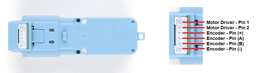
- G (Blue): hall power negative
- H1 (Green): hall H1 output signal, square wave
- H2 (Yellow): hall H2 output signal, square wave
- V (Orange): hall power positive
- M+ (Red): motor positive pole
- M- (Brown): motor negative pole
Core Skill: Robotics
This skill concerns mechanical and robotics knowledge. You may need to know how mechanical parts interact, how motors work, or how to use motor drivers and controllers.
Skill Level: Rookie - You will be required to know some basics about motors, basic motor drivers and how simple robotic motion can be accomplished.
See all skill levels
Core Skill: Electrical Prototyping
If it requires power, you need to know how much, what all the pins do, and how to hook it up. You may need to reference datasheets, schematics, and know the ins and outs of electronics.
Skill Level: Rookie - You may be required to know a bit more about the component, such as orientation, or how to hook it up, in addition to power requirements. You will need to understand polarized components.
See all skill levels
Comments
Looking for answers to technical questions?
We welcome your comments and suggestions below. However, if you are looking for solutions to technical questions please see our Technical Assistance page.
Customer Reviews
3.5 out of 5
Based on 4 ratings:
1 of 1 found this helpful:
Great motor
Works exactly like expected!
I am happy with my purchase.
Effective and prompt shipping, thank you!
1 of 1 found this helpful:
Works
Um, the wiring on the motors I just received are in reverse order of what is posted under features. I like the built-in encoders.
The latest batch has the wires the way it's stated here. Go by right to left and not color.
Hey, I'm having a lot of fun with these motors. I was having trouble getting a good number for rotation so I took one apart and found that the gear ratio is 1:45 and that there are 3 encoder magnets, so for 1 wheel rotation you have 3*45=135 encoder rising edges.
1 of 1 found this helpful:
Confirming... Cable is reversed
Motor is on Green and Purple. Encoder is Brown, Red, Orange and Yellow.
1 of 1 found this helpful:
Weak Power
I just got these motors after waiting for new stock, Jan 2021. They are weaker than the non-encoder version - yellow DG01D. I did some testing and it could lift less than 1/3 the weight of the yellow one. All 3 I bought had the same weak power. I took it apart and compared the motor to the yellow one. They look exactly the same however this one turns chunkier like there are stronger magnets inside. I don't think there would be enough power to drive a wheel in a typical application unless you went to 9 volts. Only the final gear and shaft is metal - all others are plastic.
What is the resolution of the quadrature encoder? How many ticks are there per revolution of the motor shaft? Who manufactured these and can the resolution be improved with different encoders? Is there a page with encoders that would fit?
And is there a fritzing library that includes this part?
Purchased four DG01D-E’s at end of June 2020. All four worked as expected. Average measurements of all: No-Load Volts:RPM ranged from 3VDC : 44RPM linearly to 9VDC : 157RPM with 4.5 VDC : 73 RPM. No-Load current ranged 3VDC : 15mA to 9VDC : 27 mA. Stall currents – 4.5VDC : 154mA, 6.0VDC : 199mA, 7.5 VDC : 254mA. All H1 and H2 signals were uniform 50% duty cycle square waves. When voltage was applied + to M+ (red wire) and ground/- to M- (brown wire) H1 lagged behind H2 by 16.7% or 60°. I assume the offset is a best practice for quadrature encoders. Measured 135 H1 pulses per output shaft revolution. H1 and H2, rising and falling signals should result in 540 state changes per revolution. Without disassembly I can’t confirm gear ratio or number of encoder disk poles. I also purchased the 65mm wheels (ROB-13259) and removed the rubber tire which left a 48mm diameter pulley of sorts. I attached a variable weight (pill bottle with pennies) to a string did some rough lift load experiments. Results for approximately half No-Load RPM at 24mm from output shaft: 4.5VDC : 90g : 90mA : 35RPM, 6.0VDC : 120g : 112mA : 52RPM, 7.5VDC : 150g : 140mA : 66RPM
Awesome, thanks for the test results! I'm sure this will be useful for other users.
How many poles on the encoder disk? I looked through the documents, but can't find anything that tells me counts per tail shaft revolution.
Hi dbc, Thanks for reaching out. I recently used these on a bot project (Enginursday post) and was getting about 600 pulses per revolution (of the wheel).
My project is using an Auto pHAT for raspberry pi. On that board, I have a dedicated ATTiny84 with custom firmware that is listening to the encoders. You can see that firmware here. Hope this helps and good luck! -Pete
I wish this were documented! The oscilloscope screenshot in the pdf seems to indicate the encoder pulses coming at around 1 kHz, which (very, very rough order of magnitude estimate with lots of assumptions) suggests around twelve poles on the (pre-reduction-gear) motor shaft.
What is the name of the type of connector on the motor?
JST-PH 6-pin
It's not specified in the datasheet, but the motor does come with a cable.
do you guys carry a compatible mount plate and a shaft extender for this motor?
I hooked up another encoder to the output shaft. With an input voltage of 4.5 V (with a good regulated DC power supply) the shaft appears to spin at around 70 RPM, not 90 RPM as advertised. FWIW, the frequency of the signal from the internal encoder was 166.7 Hz (with slight variations). And I get a square wave from only one of the outputs; the other one just makes blips.
This thing is kind of useless if you don't know how fast it turns or how many pulses per revolution you get from the encoder.
Any plans to offer a Qwiic board for a pair of these? (Yes, I know there is a qwiic motor driver, but I'm asking about one that also supports the encoders, maybe with some encoder-enabled position/velocity commands)
Not sure, but I would suggest signing up for our newsletter (bottom of the page), so you don't miss out (if we do)... or check back every Friday, when we do product releases.
Does anyone have output torque measurements (or estimations)?
That isn't simple to estimate as it would also be dependent on how you are driving/powering the motor.
Do these work easily with your three layer chassis (https://www.sparkfun.com/products/14339)?
i.e., do they have the same footprint (or close enough) as these: https://www.sparkfun.com/products/13302?
If the encoder was removed this would be the same footprint as 13302. From my experience with ROB-14339, there is enough space for the encoder out the back. Thanks!
Trying to get up and running with these on a Raspberry PI. Does anyone happen to have a python snippit of code to read the encoders?
This looks like a cut-and-paste of an Alibaba description. And Hall is capitalized when writing about a Hall sensor. Anyway, it looks plenty useful but I can't make sense of the description. Same description here https://core-electronics.com.au/hobby-motor-with-encoder-metal-gear-dg01d-e.html
Is this gear box a reduction ratio?
I would say it is a reduction gear box as the output shafts aren't running at blazing speeds with 5V.