Enginursday: Two-Wheeled Robot Precision Driving with Encoder Feedback
Using encoder feedback to control two DC motors, this robot is self-correcting!

My challenge seemed simple enough: I wanted to make a two-wheeled robot drive a straight line using feedback from a set of wheel encoders. Little did I know that this would open the doors into the vast world of PID motor control!
Background
Prior to starting this project, my experience with two-wheeled desktop robots had been pretty minimal. I had helped teach a few classes to educators using the SparkFun Redbot - this involved helping our participants get set up and coding challenges such as line-following and driving a pattern. We used manual “trial and error” to match motor speeds, and then used delays to control distance traveled. Although this is a wonderful introduction to coding and robotics, it’s not quite ideal for driving a very straight line and/or a precise distance. Seeing these challenges in the classroom planted the seed for this project. I knew there had to be a fun way to incorporate some high resolution encoders to augment driving control!
Hardware and approach
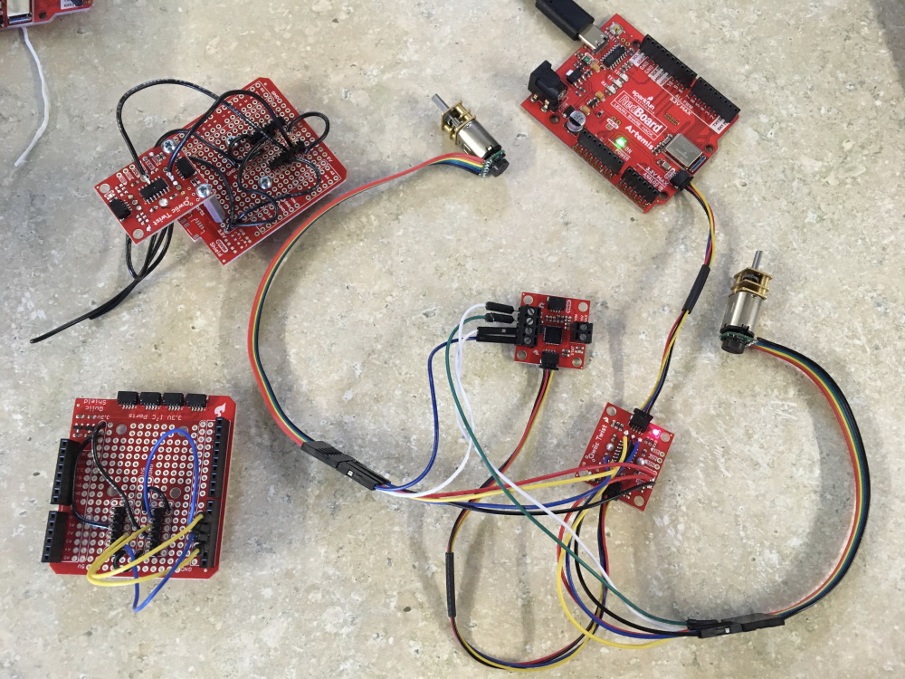
After researching many options, I ultimately decided to go with the Qwiic Motor Driver, a set of geared DC motors that included quadrature encoders, and a Raspberry Pi 4 as the master brain.
Using a Raspberry Pi 4 as the controller had two very handy benefits: First, my program would be written in Python, and second, I was excited to have the capability to adjust the code and see streaming data in real time via a Wifi and VNC viewer.
Choosing a method to read the encoders was a bit of a longer story. My previous experience with encoders involved user interfaces and turning knobs. This involved a lot of interrupts firing to keep track of the pulses and ultimately a “position from zero.” Although it would be possible to wire up the encoders directly to GPIO on the Raspberry Pi, I wasn’t interested in bogging down my Python program with interrupts.
I ultimately found the SparkFun Qwiic Twist, and decided to do something similar. The Twist utilizes an ATTiny84 to handle reading a single encoder. It keeps track of a count variable that is then easily read from the Twist via I2C. I chose to use this design and firmware as a starting point.
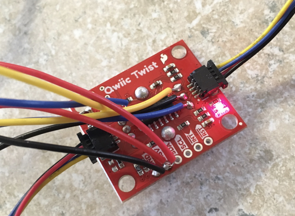
I stripped out the LED and button control and was able to utilize a second interrupt and more GPIO to read a second encoder. Wahoo! I had my dual encoder reader, and my counts would be available on the I2C bus!
To modify the Twist firmware I actually developed with an Arduino Redboard Qwiic first (acting as an alternative to the ATTiny84). This allowed me to use the UART port for debug while finishing up the modifications to the firmware (most importantly, adding support for a second encoder).
Let’s drive!
After wiring everything up, I simply set the motors to the same “power” and watched what happened. Wow, motors can vary a lot! My robot was turning sharply to the left, meaning that the right motor was actually out-performing the left motor by a lot. Now it was time to jump into some encoder counts and see if we could correct this difference!
This is the portion of my code that commands driving the straight line:
for i in range(0,300):
    count12_delta = myEncoders.count1 - (-myEncoders.count2)
    error_change = count12_delta - prev_count12_delta
    motor_speed_correction = count12_delta
    motor_speed_correction *= P_gain #proportional adjustment
    motor_speed_correction += (I_gain * error_change) #integral adjustment, looks at the change in error, if it gets smaller, than slow down the correction
    left_motor_speed -= motor_speed_correction
    myMotors.set_drive(L_MTR, L_FWD, (left_motor_speed))
    print("1:%d \t2:%d \tLS:%d \tRS:%d \tCD:%d \tEr:%d \tMC:%d" % \
                  (myEncoders.count1, -myEncoders.count2, left_motor_speed, right_motor_speed, count12_delta, error_change, motor_speed_correction))
    prev_count12_delta = count12_delta
As you can see here, I'm using a very simplified quazi-PID control system. You may also note that I'm not yet incorporating a derivative correction (this may come as a later improvement).
To start, I look at the delta between each count, and then deciding whether to adjust the left motor by a specific amount (motor_speed_correction). The correction is actually set initially as just the difference in counts, and then my proportional gain is amplifying this by a set gain (P_gain). The integral adjustment comes from looking at the change in the error. If the change in error is getting smaller, then it adjusts the amount of correction.
The turn around portion of the code looks like this:
for i in range(0,300):
    count12_delta = abs(myEncoders.count1) - (-myEncoders.count2)
    error_change = count12_delta - prev_count12_delta
    motor_speed_correction = count12_delta
    motor_speed_correction *= P_gain #proportional adjustment
    motor_speed_correction += (I_gain * error_change) #integral adjustment, looks at the change in error, if it gets smaller, than slow down the correction
    left_motor_speed -= motor_speed_correction
    myMotors.set_drive(L_MTR, L_BWD, (left_motor_speed))
    print("1:%d \t2:%d \tLS:%d \tRS:%d \tCD:%d \tEr:%d \tMC:%d" % \
                  (myEncoders.count1, -myEncoders.count2, left_motor_speed, right_motor_speed, count12_delta, error_change, motor_speed_correction))
    if(myEncoders.count1 < -575):
        break
    prev_count12_delta = count12_delta
It is very similar to the straight line command, however I now flip the direction of the left motor and took the absolute value of its count. Then I also added in a check on count1 to break out of this for loop once the desired rotational travel has been reached. In this case, the value 575 seemed to be about a perfect 180-degree turn.
Going further
I have two things I'd like to try next:
- I intend to look at each motor's speed (rather than just looking at the current count value). This would allow me to try and match each motors speed individually. I gave it a shot in the Python code, but I would really love to offload the speed calculations to the ATTiny84, so that will involve modifying that firmware again.
- I would also like to improve upon my PID method. Currently, I am actually only incorporating the proportional and integral gains, so I would like to modify this eventually to include a derivative correction.
Do you have any experience with driving similar desktop rovers? Any ideas for improving my system would be much appreciated. Thanks, and happy driving!


I've done this with the Arduino, and the parallax boebot encoders with students. They have worse resolution than your encoders (64 per wheel turn). And the motor were just servo's .
My observation, a difficulty with initial conditions having the wheels out of phase, we didn't get into any method of PID loop tuning, and I wish there was some good examples on that because it is seriously beyond what I am comfortable with.
I believe that you error_change is getting the derivative, integrals would be a running sum of error. I always tune the derivative last, after doing the I term.
Hey #812, Thanks for chiming in here!
I had some fun tweaking the Twist firmware to get better resolution. I'm currently getting about 600 ticks/per revolution of the wheel. These motors are geared ~50:1, so that helps get more. Initially I was only getting about 150, but then I dug into the Twist and found that it was actually looking for 4 "directional pulses" to report back a single tick. This is due to the fact the encoder on it has indents.
Yes, it seems that most motor manufacturers don't seem to be very consistent with the phase of the motors. I was working with the Qwiic Motor Driver, and this actually allows you to change direction with commands, so that make it a little easier to swap.
In terms of PID examples, I'm hoping to build these out a bit more, and I will definitely share what I learn, and keep my comments/commits informative!
About the I vs D. I'm still trying to wrap my head around those two terms. Proportional gain seems pretty straight forward, but it's going to take a little more experimenting to really understand how the others are supposed to be implemented.
Thanks again and take care, -Pete
By phase I just meant the wheels were out of sync a sequence of encoder counts; (0,1) (1,1) (1,2) is not indicative of one wheel traveling faster than the other. I general suggest a deadband as a way of filtering that out. Your much higher tick count makes that much less of a concern. The way I think and explain the I term is that it is to filter out consistent error, one motor fast than the other, one wheel bigger than the other, the robot on a tilted surface may all create a long term bias in which wheel is moving faster than the other. Whereas the D term is simply an effort to prevent overshoot and create a smooth transition to driving straight on the line. I have found that the D term is generally prone to creating oscillation. I am not teaching control theory and have limited education and experience with it.
Thank you so much for understanding what you mean to us
Looking good! It sounds like you rewrote the Qwiic Twist firmware? If you going down the route of pulling the encoder off the Twist and re-wiring and reprogramming the board, it might be easier and cheaper to start with something more basic, like maybe the Qwiic Button breakout? I think it has the same ATiny84.
For driving in a straight line, maybe try doing some trigonometry and calculate the current distance from the center line, that will tell how far it needs to go to get back on center. Then use the PID controller to determine how to get back to center. It is kind of cool that you were able to skip the first part and just use the PID, but maybe you can improve it by using the calculated location also.
PID is a great thing to get into -- there's a deep literature on the subject and you can get into it as far as you want to.
Your control of the difference between the left and right speeds is a good idea -- I've had success controlling individual and joint speeds like that to get small robot chassis to run straight (this is generally pretty hard to do). It helps if you calibrate your motors and give them both control inputs to get them running nearly at the same speed to begin with -- the control system will have an easier time that way.
I've generally used a separate processor for motor control that can handle all the interrupts involved, as well as odometry calculations to give an estimate of where the chassis is as it runs. That requires trig functions, so I generally need a processor with floating point support. If you don't need odometry you just need to worry about raw speed enough to handle the interrupts. In that case, too, you need I2C or SPI client support so that the motor controller can talk with your main processor.
One thing to watch out for with encoders, I've found, is that the distances between the edges you read may not be uniform. That means (depending on the actual encoder) you sometimes can't get a good speed estimate using single edge transitions. At times I've had to count edges and use the time of an entire revolution of the encoder to judge the motor speed. You can see this effect in the speed estimate -- it will bounce all around using single edges, then settle down when you start using the full encoder rotation. This is just something to watch out for.
Good luck with this going forward.
I'm not a Python guy but that code doesn't do what you say it does. The first comment already picked the derivative created by the following line: error_change = count12_delta - prev_count12_delta But then there's an integration step later on... left_motor_speed -= motor_speed_correction Think about what happens if the error is stuck at a constant = one wheel always ahead of the other. This will keep adding to (subtracting) to the speed on every step "forever". One way to recognize an integral is it can easily add up to a very large number when given enough time. So the term you call "P" is the integral and the "I" is the proportional.
Where's the full code? I'm actually interested in the ATtiny code and maybe a link to a tutorial on how you got that code onto the Twist board.
Well you are correct,should of caught that. It's not a mistake that is foreign to me.
The real problem is that we are not measuring what we are wishing to correct. Having both wheel travel the same distance isn't the same as traveling in a straight line. There are a lot of paths that aren't in a straight line that have the same distance on both wheels. This is why I now use the Line Sensor Array to introduce PID it is measuring what we are trying do. That said my test for driving with encoders is how far can the robot travel keeping the line between the two wheels, I've had robots go over 20 feet, which I thought was pretty damn good.
CENTER TURN Each wheel rotates in opposite directions, bot turns about it's axis.
Theta is the angle to turn in degrees.
Ep is encoder pulses.
N is Ep's per revolution,
W is distance between wheels, wheelbase,
D is wheel diameter,
Emm is encoder pulses per milimeter = N/Pi*D
M is the number of Ep's required per degree of turn.
M = NW/360D
Apply M*theta to each wheel but with opposite polarity
PIVOT TURN both wheels turn in the same direction but wheel on the inside turns less. Inside wheel may also be stationary and outside wheel rotates around it.
R is Radius of the turn (to the inner wheel),
W is the wheelbase as above,
Arc length is D,
For D=360 inner wheel turns 2Pi R, and the outer wheel turns 2Pi(W + R)
DD = D outer - D inner = difference in distance traveled by each wheel.
DD = 2Pi(W + R) - 2PiR = 2PiW + 2PiR - 2PiR = 2PiW
Number of encoder pulses in 360 degree turn = DD*Emm
Encoder pulses in 1 degree is (DD/Emm)/360