- Home
- Product Categories
- Logic Analyzers
- USB Logic Analyzer - 24MHz/8-Channel

USB Logic Analyzer - 24MHz/8-Channel
Is your I2C bus not ACK'ing the way you expect? Do you need to discover a UART's mysterious baud rate? Or do you want to reverse engineer an SPI protocol? These all sound like jobs for a logic analyzer! With the growing ubiquity of UART, I2C, and SPI sensors, logic analyzers are becoming a tool everyone needs in their toolbox or on their workbench. This 8-channel USB Logic Analyzer with support for sampling rates of up to 24MHz provides a good while economic option making it a great tool for quickly diagnosing most communication issues we encounter.
These analyzers will work with both 3.3V and 5V systems (up to 5.25V max and 2.0V minimum on a high logic-level) and is powered via an included USB-C cable. This logic analyzer works with PulseView -- an open-source, cross-platform signal analysis software suite.
The analyzer ships with Female-To-Female jumper wires. If you're using an Uno or board with female headers we recommend picking up a handful of Male-To-Male jumpers to connect the analyzer to the female headers.
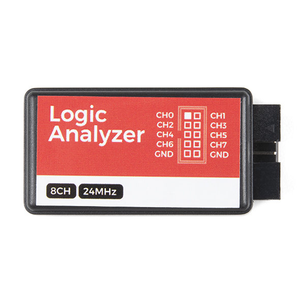
Note: On some units the GND connection that's adjacent to input six isn't actually a ground, it appears to be some sort of clock signal. We recommend not using that pin for anything just to be safe.
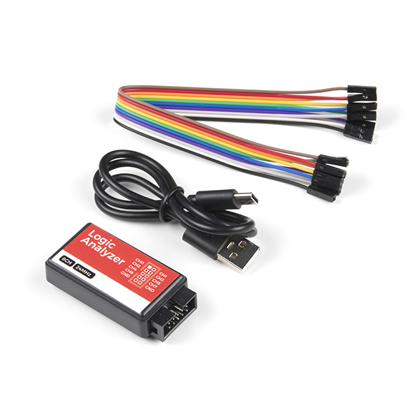
- 24MHz/8-Channel USB Logic Analyzer
- 10-conductor Female-to-Male Jumper Wires
- USB Type C Cable
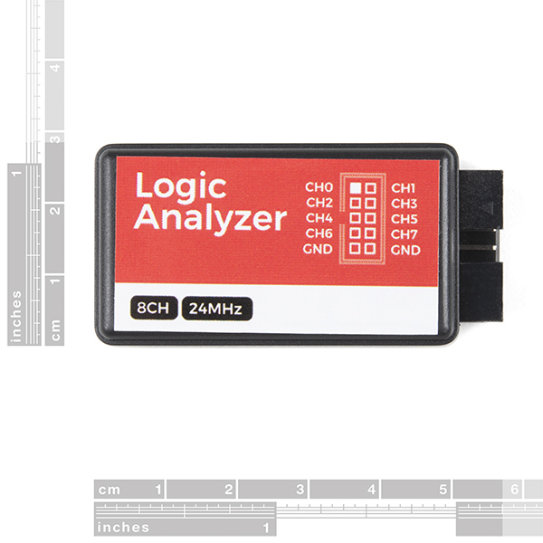
- 8-channels
- Sampling rate up to 24MHz, configurable down to 20kHz
- 5.25V maximum voltage input
- 2.0V minimum logic-high
- 0.8V maximum logic-low
- Input impedance > 100kΩ, 5pF
- USB power supply
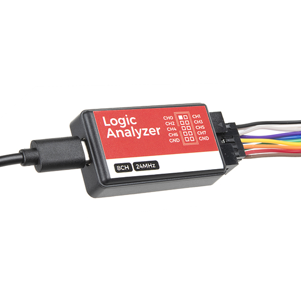
- USB Type C Connector
- Supports open-source sigrok logic analyzer software
- Cross-platform support: Windows, Mac OS X, Linux, Android, etc.
- Dimensions: 54.7 x 27.4 x 14.1 mm
With this latest revision of the USB Logic Analyzer, the USB Mini B connector was replaced with a more up-to-date USB Type C connector.
USB Logic Analyzer - 24MHz/8-Channel Product Help and Resources
2 of 2 found this helpful:
One of the GND pins in not connected.
If anyone is running into issues using this device try using the other GND pin and see if that works.
Core Skill: Electrical Prototyping
If it requires power, you need to know how much, what all the pins do, and how to hook it up. You may need to reference datasheets, schematics, and know the ins and outs of electronics.
Skill Level: Competent - You will be required to reference a datasheet or schematic to know how to use a component. Your knowledge of a datasheet will only require basic features like power requirements, pinouts, or communications type. Also, you may need a power supply that?s greater than 12V or more than 1A worth of current.
See all skill levels
Comments
Looking for answers to technical questions?
We welcome your comments and suggestions below. However, if you are looking for solutions to technical questions please see our Technical Assistance page.
Customer Reviews
3.8 out of 5
Based on 9 ratings:
1 of 1 found this helpful:
this thing is fabulous - and the open source sigroc works great!
I dearly love my 'scope. But sometimes ... I2C, some crazy display .. that's when this tool is the thing. I can't believe it's so cheap for the stuff it does. OK, it's limited to 25MHz - well, I don't work on repairing any Cray supercomputers, so that's OK.
SPI, I2C - this is the cure for pain.
I am impressed
I am truly impressed by this little logic analyzer.
Very Satisfied
Works well with PulseView
Worked better than I expected!
I was troubleshooting an i2c communication issue, and needed a low-cost logic analyzer. This one fit the bill, and worked well. I used it with the (free) PulseView software and was able to quickly fix the problem with my communication sequence. Make sure to pick up at least one pack of the mini-hooks!
Solid logic analyzer
This is a good choice if you need a logic analyzer to monitor a few GPIO and to monitor data on a few different serial protocols. I had some initial setup issues in which I couldn't capture any data. I uninstalled the nightly build of PulseView and installed the latest stable release, and then everything worked just fine.
I like the deep capture capability with PulseView. Very helpful if you need to analyze a long series of serial traffic. I used the UART protocol analyzer. It was very straightforward to setup and worked well.
There are definitely limitations with it only supporting up to 24 MHz sampling rates. However, it should still cover many use cases. Get one of these for each member of the team, and it'll cover most of your needs. It should then free up any benchtop logic analyzers for when you truly need them and not just when you need to analyze a 9600 baud UART.
Unusable
I am a Mac user. The SparkFun product description suggests that open source software is available from sigrok that will work on the Mac OS. Sadly, after receiving the device (the shipping costs were as much as the device itself!) I went to the sigrok site and clicked on the Mac OS link -> File not found. So, what would have been a fun dimension to a project I am working on is now a "use a different operating system" problem. I advise you to get the software FIRST before buying the hardware.
This link https://web.archive.org/web/20230315160737/https://sigrok.org/download/binary/pulseview/PulseView-NIGHTLY.dmg works (for now!)
Serious Capability at a Reasonable Price
Been tinkering with STM32 microcontrollers to pass the time in retirement. I purchased this logic analyzer on a whim as a debug aid for I2C and SPI seven segment displays, and if I'm being honest, I did not expect much.
Boy was I wrong.
This little device allows me to visually inspect timing and signals for up to eight channels. It even includes selectable analyzers like I2C and SPI that process and display channel content. If you find yourself in need of displaying and processing signals like this, my advice is to run - don't walk - and purchase one of these immediately!
one of the ground pins is definitely not ground
I've found the probe signals seem to be pulled up to 3.3v. This is messing with some of my existing circuit. Any way to disable this?
The includes tab says "10-conductor Female-to-Male Jumper Wires". It's actually Male-to-male as it says on the description tab.