USB Logic Analyzer - 24MHz/8-Channel

Is your I2C bus not ACK'ing the way you expect? Do you need to discover a UART's mysterious baud rate? Or do you want to reverse engineer an SPI protocol? These all sound like jobs for a logic analyzer! With the growing ubiquity of UART, I2C, and SPI sensors, logic analyzers are becoming a tool everyone needs in their toolbox or on their workbench. This 8-channel USB Logic Analyzer with support for sampling rates of up to 24MHz provides a good while economic option making it a great tool for quickly diagnosing most communication issues we encounter.

These analyzers will work with both 3.3V and 5V systems (up to 5.25V max and 2.0V minimum on a high logic-level) and is powered via an included mini-B USB cable. This logic analyzer works with PulseView -- an open-source, cross-platform signal analysis software suite.

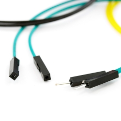
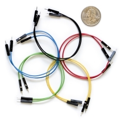
The analyzer ships with Female-To-Female jumper wires. If you're using an Uno or board with female headers we recommend picking up a handful of Male-To-Male jumpers to connect the analyzer to the female headers.

NOTE: On some units the GND connection that's adjacent to input 6 isn't actually a ground, it appears to be some sort of clock signal. We recommend not using that pin for anything just to be safe.

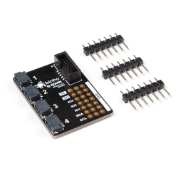
  • 24MHz/8-Channel USB Logic Analyzer
  • 10-conductor Female-to-Male Jumper Wires
  • Mini-B USB Cable
  • 8-channels
  • Sampling rate up to 24MHz, configurable down to 20kHz
  • 5.25V maximum voltage input
    • 2.0V minimum logic-high
    • 0.8V maximum logic-low
  • Input impedance > 100kΩ, 5pF
  • USB power supply
  • Supports open-source sigrok logic analyzer software
  • Cross-platform support: Windows, Mac OS X, Linux, Android, etc.
  • Dimensions: 54.7 x 27.4 x 14.1 mm

USB Logic Analyzer - 24MHz/8-Channel Product Help and Resources

Using the USB Logic Analyzer with sigrok PulseView

June 25, 2018

A quick primer on using the sigrok signal analysis software with our 8-channel, 24MHz USB logic analyzer.

Core Skill: Electrical Prototyping

If it requires power, you need to know how much, what all the pins do, and how to hook it up. You may need to reference datasheets, schematics, and know the ins and outs of electronics.

3 Electrical Prototyping

Skill Level: Competent - You will be required to reference a datasheet or schematic to know how to use a component. Your knowledge of a datasheet will only require basic features like power requirements, pinouts, or communications type. Also, you may need a power supply that?s greater than 12V or more than 1A worth of current.
See all skill levels


Comments

Looking for answers to technical questions?

We welcome your comments and suggestions below. However, if you are looking for solutions to technical questions please see our Technical Assistance page.

  • Member #213928 / about 5 years ago / 2

    For robust/easy connection to logic analyser, strip ribbon of 10-cores black-to-white from jumper wires set PRT-12794, crimp 2x5 IDC box connector (eg. DigiKey 732-2102-ND) mid-way along wires, black core to pin 1 thru white to pin 10. Gives male/female lead set with channel lead colours matching PulseView channel trace colours.

    • santaimpersonator / about 5 years ago / 1

      Just to elaborate on the previous comment. Here are links to products mentioned:

      If you split the wires into the following order and crimp them, the connections will match the colors of the connections in the PulseView and the Saleae Analyzer software:

      [Blk][Brwn][Red][Org][Ylw][Grn][Blu][Prp][Gry][Wht]
      

      (*For the crimp connector, match the black wire to the side that the arrow indicator is on.)

      • Member #213928 / about 5 years ago * / 1

        Just to correct the previous comment. A ribbon of 10 still-joined cable cores (blk)(brn)(red)(org)(yel)(grn)(blu)(pur)(gry)(wht) should be stripped from the PRT-12794 cable set; these 10 cores do not need to be split and re-ordered before being crimped into the IDC box connector. Assembled Image

  • Patronics / about 3 years ago / 1

    Does anyone know whether the PulseView software that this is suggested to be used with supports the new Apple Siicon macs? I can't seem to find any documentation on that, one way or the other.

  • mikedoug / about 4 years ago / 1

    I posted this in a response to a forum post about strange behavior with GND, but this information needs to be out there more broadly.

    WARNING -- GND NEXT TO CH6 NOT GND!

    I just went through two days of troubleshooting this device to figure out why my rotary encoders stopped working properly when I plug my GND into the GND next to pin 6... It's because that pin is NOT GND on this device!!!

    Sparkfun -- you need to put out an advisory, update your instructions, and stop printing your label like this. I bought your specific branded version because I had put a higher level of trust and faith into your products because you seem to be operating at a higher level of responsibility. But, to see you say that you don't own the board and don't have schematics is a pretty bad response to provide your customers when I spent 2 minutes to visually trace that pin back to the CLKOUT/PE1 of the CY7C68013A-56 chip. It literally lands on the third pin clockwise from the "dot" (pin 54) on the chip -- https://pdf1.alldatasheet.com/datasheet ... 3A_08.html page 19 shows that is NOT GND. It's next to GND, but "close" doesn't work in this world.

    As my first experience of buying a product that you guys sell as your "own brand", finding no real instructions for it other than your "tutorial" post saying "Also connect on (sic) of the GND wires to GND." It blows my mind -- and you've even had customers telling you that something was off with the device.

    Hopefully you receive this information well and you update what you need to update to inform your customers (past and future) about the true nature of the "GND" pin next to Channel 6.

    Thanks goes to "Junior Patrick" on the Espressif MCUs Discord for pointing out that a different "brand" of this same board labeled the other pin CLK. It got me to actually do this tracing to discover the truth behind why the device was making my project misbehave.

  • loodacris / about 4 years ago / 1

    How does this compare to the Bus Pirate?

    • santaimpersonator / about 4 years ago / 1

      Without getting technical the Bus Pirate is more versatile like a pocket knife; while, the Logic Analyzer is a specific tool, like a fillet knife.

  • Hmmm / about 5 years ago / 1

    Why does the description say 25 MHz when the product has a 24 MHz label on it?

    Is this a clone of the old Saleae Logic?

    Does it support streaming mode where it records continuously for as long as you have system memory to store it?

  • Member #1577987 / about 5 years ago / 1

    Is there an input buffer or any voltage level/polarity protection built into this?

  • Member #1575975 / about 5 years ago / 1

    Hi I would like to order one but is there any issue of installing the driver on Windows 10?

  • Member #187451 / about 5 years ago / 1

    On Windows 7, 8, 10, the device was not recognized automatically. My recommendation is to install Zadig before using the device. Run Zadig and plug the Logic device (it will pop-up in the Zadig drop-down as unknown device). Within Zadig; rename the device to something meaningfull (e.g. "SFE USB Logic Analyzer" - this is the name that will show up in Windows Device Manager), and install the WinUSB driver. From there on when you run Sigrok Pulseview, the Logic device will show up as Saleae Logic Analyzer.

Customer Reviews

3.9 out of 5

Based on 16 ratings:

Currently viewing all customer reviews.

1 of 1 found this helpful:

Works perfectly

I installed PulseView on linux, it does what is expected. I'd recommend getting a male/female wire with it so you can use it on a proto board more easily.

Haven't been able to use it yet!

Not having any luck loading drivers. Program was crashing on startup, loaded C++ to fix that, now it doesn't find the device drivers. Zadig doesn't seem to help. Windows 10 64 bit laptop. PK

It's a full-blown logic analyzer for $20

I'm old enough to remember budgeting $40k for a 2nd-tier logic analyzer--having one at home is just unreal to me. Don't debug hardware without it. You will want to buy the Bus Pirate cable (https://www.sparkfun.com/products/9556) to go with it--it's much more convenient to have the single connector to plug into the logic analyzer than fiddling with 10 individual cable ends.

Works Great

I've used this to reverse engineer a three wire SPI protocol and inspect an I2C bus. So far it works exactly as advertised. Using the PulseView software with it is very easy and straight-forward. Overall I'm very impressed with what you're getting for the price.

This thing is great!

For $20, how can you beat this? I was trying to debug an SDIO interface between an MCU and uSD card. This thing combined with the open source PulseView software, and voila, I got tons of insight into what's going on. Even at just 24MHz, this is fine for most of the projects I'm working on. I highly recommend it!

Three channels not working

Received my logic analyzer yesterday and checked it out this morning using PulseView to read PWM signals from my Teensy. Unfortunately, I was able to determine that channels 1-3 weren't reading at all. I don't need the full set of 8 channels so I can make do, but it's still disappointing.

It sounds like you received a defective unit! Please send a RMA request and we can get that fixed for you.

Cheap useful logic analyzer

Very much plug and play. Installed pulse view on ubuntu 18.04 (linux) Installed the driver package Plugged LA into UART application Works well.

Actually pretty good

I own a number of Saleae logic analyzers and wanted to try this out for kids to use to learn and debug I2C, Serial, SPI, etc... I didn't expect much from it as other inexpensive logic analyzers I've looked at were disappointing.

I also expected Pulseview to not work that well given it was free. I expected it to be hard to install/configure/etc.

Just the opposite... Installation was a breeze and performance was excellent. Recording millions of samples didn't tax the analyzer nor my PC.

The ONLY issue I dislike is the wiring. It seems silly to use female/female wires on this thing but I understand they are just trying to keep the costs down. Other people recommended purchasing the bus pirate cable adapter and if you don't mind the $5 it is probably worth it. https://www.sparkfun.com/products/9556

Amazing Value!

I've wanted a logic analyzer forever and in the past few years, the price of some had become quite reasonable. Still I hadn't found myself in a position where I absolutely needed one, and so I hesitated to buy one. I hadn't noticed this little gem on SparkFun's site until this came up as a "Deal of the Week" in May, and as soon as I saw it I ordered it! For less than $20, how could I loose? Setup fairly simple with the help of SparkFun's "Using the USB Logic Analyzer with sigrok PulseView" tutorial, and after setting up a little Arduino sketch to generate some signals to put this thing through its paces on all 8 channels, this thing is absolutely amazing! I'd have been happy with this device had it cost a hundred bucks, and for only $15, I'm astounded! Highly recommended!

Works good, but drivers are a hassle!

Once you get this little guy up and running, it works great! However, at least on my Win 10 machine, you have to mess with the Zadig app to install the driver and if you shut down and re-start it doesn't automatically re-connect. So, the driver use/installation is frustrating and not well documented, but the analyzer itself works well with pulseview and is worth the money.

Not Bad For The Money

I needed a logic analyzer for some data interception/debugging. Didn’t have to be super fast, or support wide voltage ranges. It only needed to work at 5V logic levels. Thought about going to the usual online flea markets to find a cheapie, but gave Sparkfun a look first. Glad I did. This isn’t that much more expensive, and it worked straight away with sigrok/PulseView. Once I figured out how to connect up to the PCB (I’m new to logic analyzers), I got the data I wanted on the first shot. Good stuff. 👍

Great little tool

I've used this to look at I2C signals from my Arduino. It's really easy to use. I chose a relatively high sampling rate and was able to capture it without trouble. Sigrok is a breeze to use as well. I really like their add-on a decoder option.

0 of 1 found this helpful:

DO NOT WASTE YOUR TIME

Waited several days for this only to have wasted my time and money. Software and driver installation is a pain. Once I finally got the application to load and recognize the device after having to install the application and several drivers all separately, the "run" button in pulseview completes in fractions of a second despite having selected 20 kHz sample rate and 200k samples (which mathematically should take 10 seconds to run). And no data to be found! Garbage! Will be ordering a reputable product. Congratulations if this worked for you, but if you want a reliable product guaranteed to work and do not want to risk wasting money and more importantly time, do not bother with this.

Limited Logic Analyzer

I should have not expected much from a $20 logic analyzer, but I was still disappointed. The software was difficult to install ( MacOS Big Sur on MacBook Pro). Once installed (Pulseview 0.4.2) its OK except when it freezes which is often. The real bad part is that it will not capture any signal when the sample rate is set to over 12MHz. Not sure if this useful enough to keep.

Great product at an amazing price

Out of the box it performed great. The software installed easy (Windows 10 Acer Aspire One Notebook), is easy to use and is rich in features. I purchased it to analyze data on an SPI bus. I recommend this to anyone looking for a low cost, easy to use 8 Ch analyzer. I also purchased the IC Hook with Pigtail (CAB-09741)

crashed

The software has crashed sever times using it (Linux). The SPI decoder seems to be broken and does not show the data that is actually sent. I was using it to look at the commands sent to the slave device and never saw those hex commands. Eventually I got the program for my A/D converter working, but o thanks to this analyzer. I am going to look at a little more.