- Home
- Product Categories
- SparkX
- SparkX Qwiic 24 Bit ADC - 4 Channel (ADS1219)


SparkX Qwiic 24 Bit ADC - 4 Channel (ADS1219)
A lot of the time you just need to add more analog inputs to solve a problem. It happens. The SparkX Qwiic 24-Bit ADC can provide four channels of I2C controlled ADC input to your Qwiic enabled project. These channels can be used as single-ended inputs, or in pairs for differential inputs, running at sample rates of up to 1kHz. What makes this ADC even more powerful is that it has a programmable x1 or x4 gain amplifier that lets you "zoom in" on a very small change in analog voltage (but will still effect your input range and resolution). Utilizing our handy Qwiic system, it is easy to connect it to the rest of your system. However, we have broken out 0.1"-spaced pads too in case you prefer to use a breadboard. The analog inputs and reference pins are all broken out on 0.1"-spaced pads too. This board does not have screw terminals - there was not enough room!
The ADS1219 can use its own internal 2.048V voltage reference for measurements, or you can provide your own reference via the REFP and REFN breakout pads. You can also provide your own VDDA (AVDD) by opening the jumper and connecting a voltage to the VDDA pad. This ADC board has eight address jumpers that let you choose one of sixteen unique addresses (0x40 to 0x4F). With this, you can connect up to sixteen of these on the same I2C bus and have 64 channels of ADC. The maximum resolution of the converter is 24-bits, corresponding to 244.14nV per count at a gain of x1. At a gain of x4, the resolution is 61.04nV per count. Note: the effective resolution is limited to 20-bits.
We have written an Arduino Library to make it easy to add the ADS1219 into your project.
Note: The default I2C address of the ADS1219 is 0x40 and is jumper selectable in the range 0x40 to 0x4F. If you need to use more than sixteen ADS1219 ADCs, consider using the Qwiic Mux Breakout.
The SparkFun Qwiic connect system is an ecosystem of I2C sensors, actuators, shields and cables that make prototyping faster and less prone to error. All Qwiic-enabled boards use a common 1mm pitch, 4-pin JST connector. This reduces the amount of required PCB space, and polarized connections mean you can’t hook it up wrong.
Experimental Product: SparkX products are rapidly produced to bring you the most cutting edge technology as it becomes available. These products are tested but come with no guarantees. Live technical support is not available for SparkX products. Head on over to our forum for support or to ask a question.
- ADS1219
- Operating Voltage (VDD): 2.3V - 5.5V
- (Note: When powering with a Qwiic cable, the operating voltage is 3.3V only)
- Operating Temperature: -40°C to 125°C
- Operation Modes: Single-Shot, Continuous-Conversion, and Power-Down
- Analog Inputs:
- Four single-ended
- Can be configured as one or two differential inputs
- Separate reference voltage inputs
- VDDA (AVDD) can also be configured via the jumper and breakout pad
- Resolution:
- 24-bit maximum, 20-bit effective
- LSB size (gain x1): 244.14nV
- LSB size (gain x4): 61.04nV
- Sample Rate: 20 Hz to 1 kHz
- Combined Current Consumption (Typical): 8μA - 410μA
- 50Hz and 60Hz noise rejection
- Configurable input multiplexer
- Operating Voltage (VDD): 2.3V - 5.5V
- Sixteen configurable I2C addresses:
- 0x40 - 0x4F
- Default: 0x40
- 2x Qwiic connection ports
- Power LED (configurable)
- Dimensions: 1" x 1"
Comments
Looking for answers to technical questions?
We welcome your comments and suggestions below. However, if you are looking for solutions to technical questions please see our Technical Assistance page.
Customer Reviews
No reviews yet.
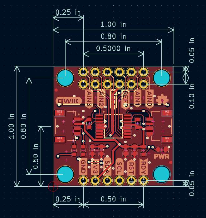
Is there a schematic available that shows the spacing of the screw holes for mounting purposes?
Hi. Excellent point. I have added one to the Documents tab and the GitHub repo: Dimensions. Best wishes, Paul
Do you intend to make the ADS1219, (SPX23455), compatible with the Open Log Artemis, (DEV19426)?
Hi, Thank you for your interest in both products. Sadly, no, not at this time. The ADS1219 Library uses the new SparkFun Toolkit, whereas the OLA firmware uses older dedicated libraries. To do the job properly, we'd need to give the OLA firmware a major overhaul. Best wishes, Paul
I also think that if the board uses a 3.3V reference by default, perhaps the code should also default to 3300mV in
float getConversionMillivolts(float referenceVoltageMillivolts = 2048.0);
Hi. I'm sure this is correct. The ADS1219 defaults to the internal 2.048 VREF voltage reference. But I will add an example showing how to use the REFP and REFN pins, and specify the reference voltage manually. Best wishes, Paul
The new example is available here. If anything is unclear, please raise an issue on GitHub - thank you. Best, Paul
I think in the bool SfeADS1219Driver::readConversion() function:
You really meant to have 0x00800000 rather than 0x00100000.
Hi, Sincere thanks for reporting this. I was testing with fixed +ve and -ve voltages from a resistor divider that must have appeared correct. I've opened an issue for this in the library repo. It will be corrected in an hour or two. Thanks again. Paul
OK. This is fixed - thanks again. v1.0.1 of the library has just gone live. You will also be able to download it using the Arduino Library Manager in about 24 hours. Best wishes, Paul