- Home
- Product Categories
- Development Tools
- GPS Shield

GPS Shield
Replacement:GPS-10710. The new version of this shield is designed to be compatible with the UP501 module. This page is for reference only.
Adding GPS to your Arduino has never been easier. The multiple GPS receivers attach easily to the shield, and with the example sketch, you will be able to locate your exact position within a few meters. Here's where we are. GPS also gives you amazingly accurate time! A GPS quickstart guide is available for this product.
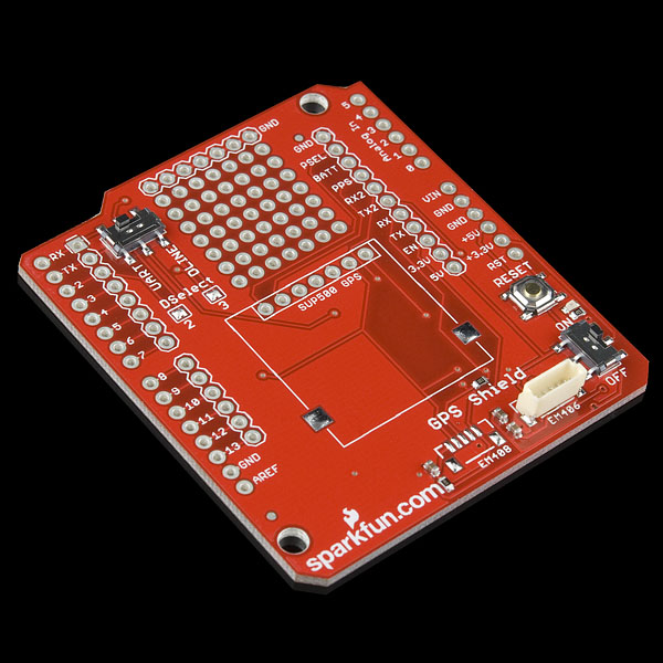
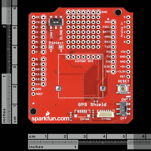
With the GPS Shield you can add GPS functionality to your Arduino. A connector for the popular EM-406 GPS receiver is populated on the board, and footprints for EM-408 and EB-85A connectors are also made available (connectors are not soldered on or included and can be found below in the related items). There is also a spot for the SUP500 GPS module. The regular GPS pins (RX, TX, PPS, etc.) are also broken out to a 10-pin 0.1" pitch header, and a small protoyping area is also provided.
The DLINE/UART switch switches the GPS module's input/output between Arduino's standard TX/RX pins or any digital pins on the Arduino (default setting uses pins 3 and 2 connected to TX and RX, respectively). The regular GPS pins (RX, TX, PPS, etc.) are broken out to a 10-pin 0.1" pitch header, and a small protoyping area is also provided. An ON/OFF switch is included which controls power to the GPS module. Additionally, the Arduino reset switch is also brought out.
**Note: **There is a new version of this shield, however, we found these in inventory so we'll be selling them at a discount for a limited time but when they're gone, they're gone!
**Note: **The DLINE/UART switch must be set to DLINE in order to upload code through the Arduino IDE.
The shield also includes the footprint for a 12mm coin cell battery holder to provide battery backup to the optional EB-85A gps module.
**Note: **GPS modules are not included with the GPS Shield, and only the EM-406 connector is populated. Headers are also not installed or included, we recommend the 6 and 8-pin stackable headers.
**Replaces: **GPS-09487
- EM-406 connector populated
- EM-408 and EB-85A connector footprints provided and connected for optional use
- SUP500 connector and footprint
- Coin cell battery socket footprint provided and connected for optional battery backup of EB-85A GPS module
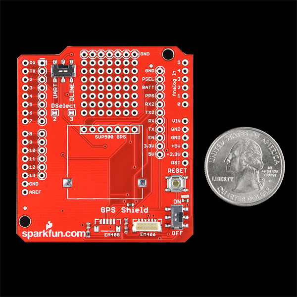
- Standard Arduino sized shield
- Prototyping area
- GPS serial and PPS signals broken out to a 0.1" header for additional device connections
- Arduino reset button
- DLINE/UART switch controls serial communications
- ON/OFF switch controls power to GPS module
GPS Shield Product Help and Resources
GPS Shield Hookup Guide
March 9, 2015
This tutorial shows how to get started with the SparkFun GPS Shield and read and parse NMEA data with a common GPS receiver.
Comments
Looking for answers to technical questions?
We welcome your comments and suggestions below. However, if you are looking for solutions to technical questions please see our Technical Assistance page.
Customer Reviews
No reviews yet.
It appears (from the schematic and a continuity test) that the EM406 PPS is not connected to the PPS break-out. Why is that? and will that be fixed in a later revision of the shield? Thank you!
If you're making another revision... being able to switch the GPS power from an Arduino pin would make this super useful for battery powered applications.
Just don't solder in a header to the 5V pin and instead solder in a wire that can connect to your desired pin. Make sure the unit doesn't draw more than 40mA though.
I've got the 3-24-10 version of this shield and accidentally broke off the top of the Dline/uart switch. Which pins should I solder/jumper together to make the shield permanently in dline state?
The link to the example sketch is broken. I believe it should link to Here (looks like the sketch was updated and the version changed but the links did not.)
To change the tx/rx pins to something other than 2 and 3 all you have to do is jumper the pins labeled 2 & 3 to different digital pins correct? I have the previous version so my layout is slightly different but still the same functionality. I just wanted to double check here before i screw something up.
thanks
-Alan
actually i just followed all the connections on the pcb, nvm about the question above.