- Home
- Product Categories
- E-Textiles
- Wearable Keypad

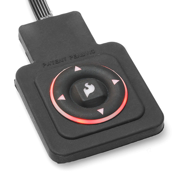
Wearable Keypad
**Replacement: **None. We don't have a direct replacement for this unit but check out our e-textiles category for more wearable tech! This page is for reference only.
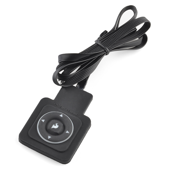
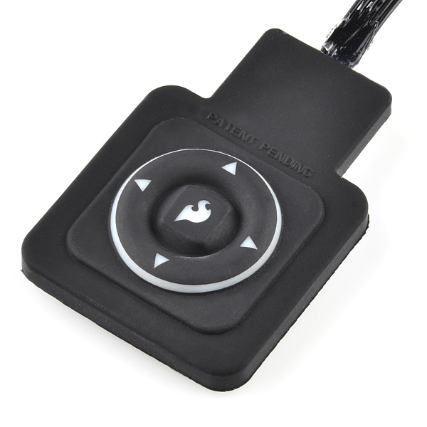
This flexible silicone keypad is all sealed up and ready to incorporate into your next wearable gadget. The button pad consists of five buttons: up, down, left, right and a center button emblazoned with the SparkFun flame. It even has a controllable red LED backlight! These would make great pads for controlling portable music players.
- [Datasheet](http://cdn.sparkfun.com/datasheets/Components/Switches/China Coin PIN out and Circuit design.pdf)
- Example Code
Comments
Looking for answers to technical questions?
We welcome your comments and suggestions below. However, if you are looking for solutions to technical questions please see our Technical Assistance page.
Customer Reviews
No reviews yet.
There's a side effect to the multiplexing: in the sample code, if down is pressed between the if (!digitalRead(p53)) return 0x01; // Down and if (!digitalRead(p53)) return 0x08; // Right sections, the code thinks right was pressed instead. It happened to me quite often (I even got it to think I was pressing left a couple of times).
what is the fix for this?
Read the pin and store it in a variable first, then do the checks?
While I know this part was retired a long time ago, I have two of them and for as long as they keep kicking I'll use them in my various wearable art projects. I for one would love to see you resurrect this part. I would buy ten of them as a hedge against future retirement because they are exactly what I need for my projects. (http://anthrolume.com)
I'll bring the suggestion back up!
Have a look there: https://forum.sparkfun.com/viewtopic.php?f=14&t=29321
With detection of short, long, double click.
While this product did have its drawbacks, I have two of them and they worked great for what I was using them for (http://anthrolume.com). I'm quite sorry to see the product go away - the form factor was really perfect, and the thing was weather and dust-proof. Please replace this product with something that has the same form factor and seven wires without the weird multiplexing.
I have to say that I'm not pleased with this product. While I understand the desire to save I/O pins, increasing the number of leads from 5 to 7 would eliminate the need for the diodes and confusing wiring scheme (and maybe reduce cost!).
The polling currently required is annoying. Not only does it mean running the poll code when the processor could be doing something else, it is unreliable, as stated elsewhere. The need to do multiple polls to ensure an accurate reading means more programmer headache. It isn't worth 2 pins!!
Buttons are made for interrupt-driven code. AVR microprocessors' pin-change interrupts (and Arduino libraries supporting them) are easy to use and make sense for many applications. While you can set up interrups for the up/down/logo buttons, left/right will still require manual polling.
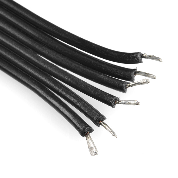
On mine, the wire order was inverted !!! The LED was at wires 4 and 5 (not 2 and 3 as per PDF).
It was easy to test, put a 3.3V between wires 2(+) and 3(G) or 4(G) and 5(+). The LED will go on and you will know the wire order.
Same to me. Thanks a lot, you save a lot of my time.
I got the LED to work but I can't get any of the buttons to function. Where is page 2 of the datasheet?
The schematic on this little gizmo is kinda screwy in my opinion. It works, but is somewhat messy in the software logic. I get that the designer was going for economy of port pins (only 3 is good), but with most *duino (or other MCU) boards, port pins are NOT in short supply.
I much prefer a clean row/column schematic, which helps the software weenies get their logic orderly. So in this product, a row/column scheme would have yielded 5 port pins (2 rows x 3 columns) and more ordered code.
< / 2 cents>
I agree with this. It would make interrupts a possibility as well
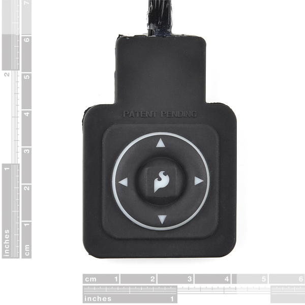
It would be really nice to have either a mechanical drawing of this gadget, or views of the side and back with the little gray ruler.
It appears I could mount it behind a control panel, exposing only the inner square bevel. It would be great to be sure.
Tell the truth, did the decision to use five active wires have anything to do with the size of the Lilypad small prototype boards? Or is it just a fortunate coincidence? I had to add solid-core wire ends, but otherwise I think this works really well, thanks! (I used it to 'draw' on my LED-matrix top: chebe.dreamwidth.org/61563.html )
hmm... looks like a custom sparkfun logo in the middle :) could we ask who supplies these to you?
I wrote an object and demo to use this keypad with a Propeller chip.
http://forums.parallax.com/showthread.php?134434-Wearable-Keypad-Object
I used 10K Ohm pull-up resistors on the button lines.
As other's have noted, the wire order is reversed in the datasheet.
I measured 34mA current when the LEDs are powerd with 3.3V.
The wire pitch is less than 0.1", but I found that it was pretty easy to crimp an 8-pin IDC connector onto the ribbon cable if you split the conductors and align them carefully.
I too would love it if the LEDs (there are actually four inside the thing) were RGB.
I'm also puzzled by the multiplexing mechanism - all that to save one wire and two diodes? You could have used seven wires(GND, LED, Left, Right, Up, Down, Flame) and no multiplexing. Plus that way you'd be able to detect all the combinations of buttons. With the current schematic, it looks like only combinations of up, down, and flame are detectable.
Nevertheless, it's a cool gizmo and I'm using it for controlling my anthrolume project (http://anthrolume.wordpress.com).
at first, my dpad just output "left" repeatedly with the example code using arudino022 w/ duemilanove. i reversed the order of the connections and now it works. the datasheet is backwards to me, anyone else?
Not that I haven't got it yet or anything, but it would be really helpful if you colored the last bit of wire or something somehow
I could technically do it, but it might be neat...
What type of buttons are being used under the pad? I understand if you can't tell me, but I need something like this, but in a different form factor, so unfortunately I can't use this keypad and need to construct my own solution.
Needs to have a blue LED.
Nah, needs to have an RGB LED.
A LED that works would be my bare minimum request... The LED on my keypad doesn't work. Doh.
Sounds usefull, but the 2nd image makes the connection to the pad look nasty. Is it poor quality, or just a bad image?
It looks like silicone residue from the molding products, because of the silicone it's not going to be as clean as a plastic pad
How long is the cable?
I received mine this week - cable is about 1 metre long.
What are the dimensions ? The data sheet says page 1 of 2, but only 1 page in the PDF :(
Check out the second image in this product page - it has the usual rulers :)
( though page 2 being included would still be nice )
Also check out today's new products video for a short demonstration;
http://www.sparkfun.com/news/601
Is it water resistant?
How strong is the area where the wire meets the housing?
It is very water resistant, but I would not submerge it in water. The unit is sealed extensively with silicon. The connection where the wires meet the enclosure also has good stress relief.
I'll let everyone know how it goes when I sew it to a jacket to control my mp3 player and after it has gone through the wash a few times. i'd be more inclined to worry about water seeping into the cable at the other end, so i'll have to water proff that end too