- Home
- Product Categories
- Sensors
- LSM303 Breakout Board - Tilt Compensated Compass

LSM303 Breakout Board - Tilt Compensated Compass
Replacement:SEN-10888. We are no longer carrying this rev in our catalog. This page is for reference only.
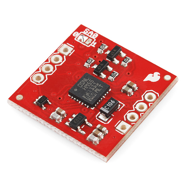
The LSM303DLH is a triple axis accelerometer combined with a triple axis magnetic sensor. This breakout board uses the LSM303DLH to give a you the data you need to feed into a microcontroller and calculate tilt-compensated output.
This version of the board has added circuitry to address concerns about voltage translation on the SDA and SCL pins.
Replaces:SEN-09810
- +- 2/4/8 g dynamically selectable full-scale
- +-1.3 to +- 8.1 gauss magnetic field full-scale
- 16-bit data out
- I2C interface
- Embedded self-test
- [Schematic](http://cdn.sparkfun.com/datasheets/BreakoutBoards/LSM303 breakout board-v12.pdf)
- [Eagle Files](http://cdn.sparkfun.com/datasheets/BreakoutBoards/LSM303 breakout board-v12.zip)
- Datasheet
- Example Code (Arduino)
- Application Notes
Comments
Looking for answers to technical questions?
We welcome your comments and suggestions below. However, if you are looking for solutions to technical questions please see our Technical Assistance page.
Customer Reviews
No reviews yet.
Since March there is a new version of the chip called LSM303DLHC it comes in a slightly different package and it only uses one 3.3V power supply. So with the new one you don't have to worry about powering and translating 2 sets of voltages like with this old one.
We're coming out with it soon.
How soon?
not quite sure, maybe a month or so. we have the ICs in stock, but are just waiting on PCBs and such.
It is still not available! Hard to believe
we're working out some testing issues with the new board.
What are the issues with the new board? As far as I can tell from the datasheets for the DLH vs. the DLM, it looks like I can drop the DLM on this breakout board in place of the DLH, unless I'm missing something.
Looking forward to the new version. I'm going to order this compass by spring and would like the DLHC, if possible. Is it still on track?
Actually, it looks like our new version will use the LSM303DLMTR.
Have you started shipping the DLMs yet?
Nope, not yet.
Any updates on the LSM303DLMTR Boards...??
So what are the voltage ratings on the various pins of this guy (VCC, SCL, SDA)?
It has voltage regulators and logic level converters. This will work with 5V (and probably 3v3) systems.
I am a little confused by these messages. I just got my Sparkfun LSM303DLH today. So do you mean that I can come in on Vin with the 5v from the arduino? I wasn't sure if you were talking about the sparkfun or the pololu.
5V to the Vin on LSM board should be fine. The voltage regulators (5-pin chips on lower part of board) coverts your 5V down to 3.3V and 1.8V needed by the LSM chip. From the exterior markings, the voltage regulator looks like Micrel 5205-3.3YM5. Google is your friend. Find the datasheets from the exterior markings of the other voltage regulator and look up anything you want to about it. Same for the level converters (3-pin chips and resistors on upper part of board).
So from what I have seen in the schematic I could power the compass by 3.3V but the 3.3V regulator will not be able to have it's output voltage at 3.3V. That will mean the compass will not be powered by 3.3V but something less will the module still work or is the output voltage of the regulator too low for the compass module to operate properly?
So this board supplies the magnetometer and accelerometer data separately?
Yes. The magnetometer is at address 0x1E, and the accelerometer is at address 0x18.
No The magnetometer is at address 0x30, and the accelerometer is at address 0x3C
Has anyone gotten this to work with a propeller? I'm having a hell of a time translating the Arduino code to spin.
A propeller, huh? Well I haven't personally worked with a propeller but first and foremost it's important to know when needing a motor to spin you will have to power it with secondary power source besides the arduino. The arduino doesn't have enough current to drive the motor alone. That can be accomplished by putting a transistor (with something like 100ohm attached to the base of the transistor) to the pin you would like to use. Then connect the motor to the secondary power supply through the transistor. Since you are using a motot it's best to use a PWM pin on the arduino.
If you already know that then next I would suggest using the arduino's "map" function. The compass module will send numeric values from 0 to 360 (as floats i.e. 0.00) to the arduino and from there you can write your code based on the values received. So the map function might look something like "PWMpipn = map(0,360,0,1023);". I can't remeber if it's 1023 or 255, but at any rate that funciton will translate the first values into the second values to be used proportionately on the PWM pin. The higher the number the faster it will spin.
This is all just a simple and fast stech to what I THINK would work...not sure if it will becuase I haven't tested it. But start there. I hope that helped in some way. Sorry if it didn't.
GOOD LUCK!
Thanks for your response Kyleser. I am using an Arduino Uno and, although I thought I checked the baud rate, I'll check it again. I'll also follow up with your other suggestions. I did notice something that seemed odd. When I check continuity across the SCL and SDA pins, I get continuity. I'm not sure if this should be the case. I thought at first it could be from my novice soldering skills so I unsoldered the puns and there was no change. Anyway, I'll check all your suggestions and get back.. Thanks for your help.
Has anyone figured out how to calibrate this compass using the Arduino language? I can't figure this out based on what the datasheet says. Someone help please!
Thanks!
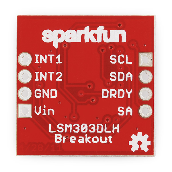
I recently purchased the LSM303DLHTR breakout board. I connected Vin to 5V, GND to GND, A4 to SCL and A5 to SDA. I also used the code example give above. I was able to compile the sketch but when I try to upload it, the serial monitor reacts as if nothing is going on. Any thoughts on what I might be doing wrong? I'm new to Arduino and don't have the best background. Any help you can provide would be appreciated.
It's either something simple or your component is bad...I'm betting it's something simple.
So first of all if your component is the exact one you bought up above (not sure what the "TR" means in the LSM303DLHTR name) then I would try the follow sanity checks.
If you AREN'T using an Arduino Uno then the I2C pins (SDA & SCL) are going to be different on a different Arduino board. The component will still work but you will have to put the SDA & SCL pins to their appropriate pins on the other boards if you aren't using the Uno.
Visually verify you are actually connecting the correct pinout of the component to the Arduino. (Not trying to insult your breadboard skills but if you are using a breadboard or the proto-sheild make sure you are connecting the pins in the correct rows/columns.)
Make sure you have the correct Arduino selected from the Tools option menu. Tools->Board-> Which ever Arduino you are using.
When uploading the code to the Arduino, I had the issue of the code being outdated with Wire.send/wire.recieve. So make sure those are corrected. (The debug messages tells you what to replace those with. It should be like Wire.read and Wire.write I think)
The final thing I would try is ensuring your baud rate is matching. In the code (and most standard cases) the baud rate is 9600, shown by "Serial.begin(9600);" this is used for the Arduino to communicate back to the computer and visually output your results. On the actual serial monitor there should be a drop down selection. Select 9600 from the list and resend the code to the Arduino.
If none of those things work I would try to select another serial port if available. Tools -> Serial Port -> pick another.
If still that doesn't work then call the Tech Support and they are very quick, friendly, and understanding about either figuring out what's wrong and give a solution or just completely returning items that don't appear to work.
I hope this helps. Good Luck and enjoy your compass!
(btw, if you do get it to work then the next step would be to calibrate it. That's where I'm stuck on right now...so if you get to that point and receive valid instructions/code to calibrate please share it with me! Thanks in advance!)
I was able to get this calibrated correctly. I have to code and process you will need if you aren't able to figure it out. Good luck and take care!
So has anyone figured out how to code this in arduino language to calibrate it? My north and south are on point but east and west are always about 33 degrees off. I need help and direction on how to calibrate it that makes sense. The data sheet does a horrible job with this.
You need to calibrate it according to the procedures outlined in the datasheet and app notes. The data sheet will reference an extensive app note that explains the calibration procedure. You will have to add code to adjust the Magnet. readings to account for span and offset settings you capture during calibration. This is not a compass, but it can be made into one and can be accurately tilt compensated as well.
Thanks for your response, however you have simply restated my question. I understand I should follow the instructions presented by the datasheet for calibration but is in fact my question. HOW am I to follow it? It is very vauge with information (granted this chip wasn't made specifically to be used by the Arduino language) on how to make calibration code to run. That's what I am asking. So going back to my original question, does anybody know how what the code is for the Arduino language in order to calibrate this chip?
I see in the scheme that it has the pullups and little mosfets on the SDA/SCL lines. That means that it is ok to use SDA/SCL direct off of the arduino without a level shifter, correct?
Links to the datasheet and application notes seem to be 404...
I want to use this on the same I2C bus as another device that has a LSM303DLM (not H.) The addresses collide. The "M" version has a "WHO_AM_I_M" register to change the I2C address it recognizes, at offset 0xF. Offset 0xF is not documented for the "H" version. Will the "H" ignore a write to register 0xF? If so, I could tease these two apart by outputting a new address to that register the first thing I do; the "M" will switch address, and the "H" will not.
Turns out, WHO_AM_I_M is read-only, so you can't change the address. This unit will collide with any other LSM303 based unit on the bus.
does anyone has experience or example code to hook this up to an arduino?
Does anyone know what the maximum update rate is for this?
What is the allowed range for Vin?
Just to let you guys know the arduino library for this compass is not compatible with arduino rc1 yet. (10/1/2011)
I do not have sparkfun's version of the board, I have pololu's. Anyhow the accelerometers on this chip are very noisy causing the reading to waiver a lot. The magnetometer is fairly decent however.
This would be perfect! Do you know of any similar to this thats just a bit smaller??