- Home
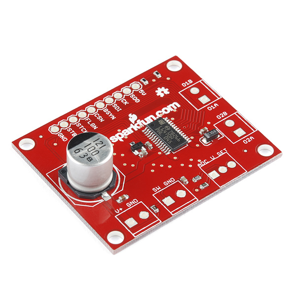
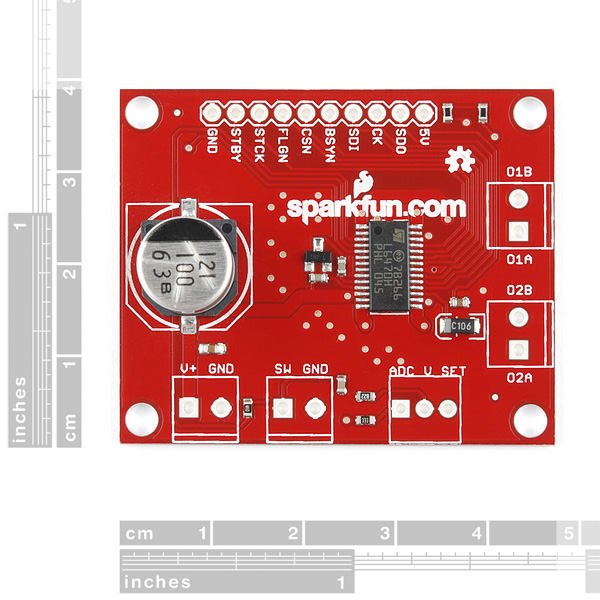
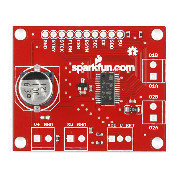
- L6470 Stepper Driver Breakout

L6470 Stepper Driver Breakout
Replacement:BOB-11611. We've completely overhauled this board, go check out the new version now! This page is for reference only.
STMicro's L6470 (a.k.a "dSPIN") is a 3A, 8-45V bipolar stepper motor driver. It has built-in overcurrent detection, undervoltage detection, overtemperature detection, stall detection, a 5-bit ADC, and a switch input that can be used for either user jog control or as a hard stop function. As if that weren't enough, it also features microstepping support (up to 128 microsteps per full step) and PWM drive voltage limiting.
Unlike most stepper motor drivers, the dSPIN is controlled over an SPI link. It has an on-board 16MHz oscillator which allows it to autonomously execute movement commands. That means no more counting steps in your code! It also supports customized acceleration and deceleration profiles to prevent jerky starts and stops. On-board registers track current speed and location.
This L6470 Stepper Driver Breakout makes it easy to put the dSpin to work in your project. Simply connect your motors and your SPI-capable microcontroller and get steppin'! The logic supply voltage supports both 3.3V and 5V I/O levels.
- Supports up to 128 Microsteps per Full Step
- Over-Temperature Detect
- Over-Current Detect
- Under-Voltage Detect
- PWM Drive-Voltage Limiting
- SPI Controlled
- On-Board Oscillator and Speed/Location Registers
- Stall Detection
- 5-bit ADC
- [Schematic](http://cdn.sparkfun.com/datasheets/Robotics/L6470 breakout-v11.pdf)
- [Eagle Files](http://cdn.sparkfun.com/datasheets/Robotics/L6470 breakout-v11.zip)
- Datasheet
- Example Sketch
L6470 Stepper Driver Breakout Product Help and Resources
Core Skill: Soldering
This skill defines how difficult the soldering is on a particular product. It might be a couple simple solder joints, or require special reflow tools.
Skill Level: Rookie - The number of pins increases, and you will have to determine polarity of components and some of the components might be a bit trickier or close together. You might need solder wick or flux.
See all skill levels
Core Skill: Robotics
This skill concerns mechanical and robotics knowledge. You may need to know how mechanical parts interact, how motors work, or how to use motor drivers and controllers.
Skill Level: Rookie - You will be required to know some basics about motors, basic motor drivers and how simple robotic motion can be accomplished.
See all skill levels
Core Skill: Programming
If a board needs code or communicates somehow, you're going to need to know how to program or interface with it. The programming skill is all about communication and code.
Skill Level: Competent - The toolchain for programming is a bit more complex and will examples may not be explicitly provided for you. You will be required to have a fundamental knowledge of programming and be required to provide your own code. You may need to modify existing libraries or code to work with your specific hardware. Sensor and hardware interfaces will be SPI or I2C.
See all skill levels
Core Skill: Electrical Prototyping
If it requires power, you need to know how much, what all the pins do, and how to hook it up. You may need to reference datasheets, schematics, and know the ins and outs of electronics.
Skill Level: Competent - You will be required to reference a datasheet or schematic to know how to use a component. Your knowledge of a datasheet will only require basic features like power requirements, pinouts, or communications type. Also, you may need a power supply that?s greater than 12V or more than 1A worth of current.
See all skill levels
Comments
Looking for answers to technical questions?
We welcome your comments and suggestions below. However, if you are looking for solutions to technical questions please see our Technical Assistance page.
Customer Reviews
No reviews yet.
thank you thank you thank you sparkfun! I don't know who convinced you guys to do this but I am ever so very grateful. I was going through the painful process to designing such a board myself. Now I don't have to. To God be the glory.
Hi together,
I was very satisfied running l6470 with low-cost and low-torque Motor. But now I bought an SECM264-E2.0 Stepper that is Microstepp optimized and have a nice Torque.
So I would like to use it in Bipolar Parallel Mode and the Data for that would be: Current/Phase: 2.8 A (would like to use it at 1,8 A) Resistance/Phase: 0.7 Ohm Inductance/Phase: 1.4 mH
But I don’t want to push the Motor and Driver Chip to the Edge so I would set it to 1,8 Amper! BEMF Compensation gives me those Values:
//parallel with 1.8 Amper
dSPIN_SetParam(dSPIN_KVAL_HOLD, 0x07);
dSPIN_SetParam(dSPIN_KVAL_RUN, 0x26);
dSPIN_SetParam(dSPIN_KVAL_ACC, 0x26);
dSPIN_SetParam(dSPIN_KVAL_DEC, 0x26);
Now it comes the tricky Part. I have to run this Stepper at Speed around 2 Steps/Second !!!
At this speed and this low Voltage (1,8 V) Motor makes very very strange and absolute not satisfied movement. I know that there is an option called SetLSPDOpt in Script, but setting this at true does make no difference.
It seems that this drive is not suitable running strong stepper at low speed?
I tried connecting it in serial so that at least Voltage would be bigger, but here my Motor would become hot after 5 Minutes running low Speed.
Did someone noticed those problems or am I the only one?
We ran into problems reading ABS_POS on an Arduino board, too. The problem seems to be in the dSPIN_Param function in file dSPIN_support.ino.
C silently converts types shorter than int to int prior to any arithmetic operations. Ints in Arduino are 16 bits, so the left shift operations on the bytes returned by dSPIN_Xfer don't work as intended with 16 bit ints.
Consider how dSPIN_Param handles the first byte returned from dSPIN_Xfer:
dSPIN_Xfer returns a byte, and it is silently converted into a signed, 16 bit int, and then it is left shifted 16 bits. A 16 bit value shifted left 16 bits is 0. So the most significant byte of the ABS_POS is effectively ignored. Surprise #1.
The next byte is handled the same way, except it's shifted left 8 bits, but this also causes an unexpected result. Suppose dSPIN_Xfer returns 0x80. It's first converted to an int (0x0080), then shifted left 8 bits (0x8000). But this is now a negative value in a (signed, 16 bit) int. So when it's converted to an unsigned long to be OR'd with ret_val, it's converted to 0xFFFF8000. Surprise #2.
The solution that worked for us was to explicitly cast the value returned by dSPIN_Xfer to an unsigned long. This forces the conversion of the 8 bit byte to a 32 bit value, which is long enough to handle the left shifts properly.
(It's not strictly needed in the last case, but I like consistency.)
I suspect the original code was written for a system that used 32 bit ints, on which the left shifts would have worked as intended.
I hope Sparkfun will change the example sketch to save other from this subtle bit of C behavior.
Hey thanks for posting that :)
I had problems with ABS_POS too and I suspect you've got the solution.
Thank you, Joe P. -- I was also getting weird values for ABS_POS. After I fixed dSPIN_Param() by sprinkling "unsigned long" casts as you recommended, ABS_POS now works great -- thank you!
Hello. While I don't have this board yet (or any dSPIN to play with at all) I can tell you that your problem is a platform problem. Note that the C standard does not offer any guarantees as to the number of bits of each type. In fact, even the "byte" that we take for granted today, used to be anywhere from 5 to 12 bits!! While I don't think you'll run into that anymore, you have to throw out your assumptions about data size of C types and determine what your compiler is specifically doing for each C type on a specific platform. Otherwise, best case, you're code will not work and you'll be frustrated in trying to solve it and in the worst case, you're code will work fine until one day when you do something over that bit threshold, when your robot arm slaps you in the head. (OK, so that was probably a very weak attempt at a "cautionary tale" :)
So I suggest that you consider type-sniffed types from the posix library (i.e., your libc) implementation instead of the standard types "long", "int", etc.
EDIT: it's not letting me use angle brackets in the code example :( but the stdint.h, should be <stdint.h>
See also: <stdint.h>
Hi Joe P.. I was testng your idea but dont works...im experimenting for a long time this bug.. all works except this ABS_POS register..
Come on Sparkfun! are you going a upgrade this code?? awesome chip but this is a very very bad problem.. people will not buy this board with this kind of errors..
In your dSPIN_example sketch I see an anomaly. In the file dSPIN_support.ino the function AccCalc claims to need to multiply stepsPerSecPerSec by 0.137438 but that figure is not supported by the maths:
According to my calculations the required value would be:
Not 0.137438.
The inverse of 0.068719476736 is 14.551915228367.
That agrees with the datasheet (page 40) which says:
And multiplying 14.551915228367 by 0x8a gives 2008.1643015146 which is what they say the default setting for the ACC and DEC registers are.
Am I missing something? Is the datasheet wrong? Or the code wrong?
The other calculations in that file check out, it's just this one that doesn't match up.
Ditto for DecCalc of course. It uses the same figure.
Question: If the absolute position counter is +/- 2^21, and I am set for 1/128 uStepping with a 200 steps/rev motor, then I can only turn the stepper +/- 81.92 revs from zero before losing my position???
That's correct. If you want to keep track of more revolutions, you can reset the counter and keep track of the value yourself when it starts to get on the high end of things. You should probably only do this with the motor stopped though:
Call this code whenever your motor stops. If you want the current motor position at any given time, you need to query the chip's counter and add it to your accumulator. Resets only happen when it's in the last quarter of its travel. This method is untested, but the basic idea should work :P
Does anyone know how can i set up the Microsteps in this driver?
Nothing is more fun that product quirks! (ST's product, not sparkfun's :) So buyer beware! The L6470 has an internal 8-bit data latch that it uses for all SPI communications (that's why it's so easy to daisy chain them on the same CS). However, it does not ignore CK (serial clock) when CS is deasserted! Thus, if you're SPI master happens to have a quirk of toggling the clock line in between messages, say like the MCP2210 does, then you'll end up with responses where each byte is shifted left a bit, LSB always zero, MSB missing.
In case you happen to run into this, you can work-around the problem with an inverter on the clock line and configuring the MCP2210 to use CPOL = 0 (so SPI mode 2), since it doesn't have this hiccup when CPOL = 0, and the inverter will put the clock back in the correct polarity.
sparkfun, on your next revision of this, can you please use the POWERSO-36 package? :) :)
Hi Techsupport Team, We ran into problems reading ABS_POS on Arduinio Board.. maybe you already know about this problem It seems to be the 8th Bit from the 22 bits Position register is always Low other reset.. All the other functions are working good but of course I don´t be able to read the Position values correctly
In Order to find the solution i´ve tried following:
Im need to ask if you could reproduce this error in your labs, it looks as many costumers have experimented the same situation. We need to be shure that your code works or we need to find other Hardware options at right time.
Thanks !
Sorry to hear you are running into issues with this. Please send tech support questions to techsupport@sparkfun.com. They should be able to help you in more detail than is appropriate for the comments section.
Actually i did it...i just want to get feedback for the others users about this topic
This is a really expensive breakout board... The part is $3.40 in volume. I understand that breakouts have a markup, but this is a lot.
Hi, after some fiddling around I got the dSpin running with an Arduino Uno. But I experience strange behaviour of the “move” command: when issuing 200 Steps it just moves a little bit, only when passing ~25000 steps it moves one whole revolution. Any ideas where that could come from ?
I’m using a Nema 1,2A 1,8° Stepper, Arduino and the dSpin. moritz
Maybe you're defaulting to 128 microsteps? Your Stepper motor has 200 steps per revolution, so: 200*128=25600. A call to move 25600 steps would be one revolution while microstepping 128 per step.
Hello, guys. I happened to use the exact same stepper driver. It is powerful without any doubt, however, I found there existed some problems. I can control my stepper with my 51-MCU, but the maximum speed of the stepper 4.5r/s, that is, 900 steps/s or 270r/min, it is too slowly! I just have no idea how to fix it. And, I found the current is just 300mA at most. Strange. Any one can help me? Thanks in advance.
OK sparkfun, it's complaint time:
Less confusing are these inconsistencies between the board & schematic:
Can guys pretty please either:
etc. Thank you!
// there has been alot of discussion as to where or not you can use the L6470 driver
// for milling machines and many other purposes where 2 or more motors
// need to be synchronized as well as have dynamically assigned speeds.
// the problem is there is no clear/actual way to change the speed register wile the motor
//is running, some have suggested to just use the L6470 in step at a time mode
// but I feel this is a waste of allot of great features ie stall detection.
// So without further adue here is a solution
Code:
if you run this you will see that the stepper s acceleration
//is nice and smooth while still being controlled dynamicaly ( wile the motor is
// running ) It is a very simple work around ...
In truth the motors speed is changing in-between move commands,
but this is happening so often that it is very smooth!
// now the comes the part thats not done yet ... daisy chaining, // using the method dynamic speed method combined with daisy chaining // one more thing ... load all the bits but one on the daisy chain while the // motor is finishing the previous command then using an interrupt as soon as // the L6470 busy pins are all low load the last bit in the daisy .. // this should reduce any delays that could cause motor noise!
Shoot me a message if you improve on it, or the methods iv spoken of.
Some links to my project related to this post
https://github.com/Rylangrayston/ard...ee/Daisy-L6470 // youcan find the full code here!
http://www.blenderartists.org/forum/...!-Suzans-Dolly
http://rylangrayston.github.io/arduino-blend/
Anyone get the L6470 to run without constantly reporting stall errors on A and B?
i wish there has been some tutorial stuff for the example sketch. so i researched, tried and errored. here's my result: Image of wiring
The schematic shows a 200KOhm variable resistor "R4" connected to "ADC" (pin 5). I looked all over the board I have in my hands, and I can't find R4 anywhere. Am I going blind?
It's a footprint for post-placement of a through-hole potentiometer. We didn't populate it to keep costs down, since I didn't think many people would find a use for it.
Hello,
Thanks for the board, it save a lot of work for me.... well almost :-) Just one question, everything seemed to be working, but I'm not sure how to use the sample code. The motor just runs back and forth calling dspin_run. I expected that it would go one full revolution for this motor (https://www.sparkfun.com/products/9238).
Can this board be used in a pure SPI mode? I only want to use SPI so I've connected only the SPI lines with arduino. In fact, in my loop I just do:
dSPIN_Move(FWD, 128000); while(dSPIN_GetStatus()) delay(500); dSPIN_SoftStop();
I'd appreciate any direction I can get. Thanks in advance guys.
cc
This gets weirder, I now have two boards, one works flawlessly over the same code/fw. While the other seems to be choking, it just rotates badly. I'd appreciate if somebody can shed a light on this.
Thanks all.
More info, the "bad" board seems to rotate only at speed 12000. But even this is noisy. Anything more or less causes it to just freeze.
My power supply is at 12 V (3A). Could this be a possible reason? What made the other board run the motor smoothly?
Hi guys,
I just plain need help here. Please don't respond with "If you don't know what you are doing then, don't try it", because nothing is more bothersome than someone telling me not to seek help.
Has anyone written a tutorial on using this break out board with an Arduino Uno R3? I know you guys are operating with a level of knowledge far above mine, but I've spent a day just trying to get the board to work with my controller and a stepper motor.
I'm suffering from the "Code is documentation" problem. It seems like anyone who has written something online about this is operating under the assumption that every reader is a programming guru. If anyone has the heart to write up a basic tutorial for wiring up a test rig, and show which calculations are important to get a motor turning then I promise I will share all my future developments with the community.
I'm hoping to use these chips to drive 3 stepper motors for a 3 Axis CNC machine, with the goal of having it up and running by April 2014. I've got a router up and running on GRBL with a CNC shield before. This is my attempt to get into the nitty gritty. Who knows months from now I could have a decent setup, but any help just getting started would be much appreciated.
Driving the steppers of a 3 axis CNC machine with L6470 chips sounds great. Would you mind writing up an outline of a basic tutorial somewhere with everything you wish you had known at the start -- perhaps using "???" question marks to fill in details you still don't know but wish you did? Would the RepRap wiki be a good place to post this basic L6470 tutorial ?
I am running into problem trying to reduce the speed once the motor is running. I am using the dSPIN_Run command, and have no trouble ramping the speed upwards, but then when I try to ramp back down by passing in lower values, the motor just keeps running at the same speed. This behavior continues until I pass in 0 (zero) as the Run speed, at which point the motor stops as expected. Note that my accel and decel params are set to 0xFFF which should give me infinite accel/decel. Min Speed is set to zero. BEMF is disabled.
What am I doing wrong?
I think I've answered my own question. It appears that the documentation is wrong when it says to set the ACC param to 0xFFF for infinite accel/decel. Instead, I set it to 0x7FF, and now it appears to be doing what I want.
Hi guys ! I am trying to connect this Easy Driver to my micro-controller. However, I do not see a "STEP", "DIR" and "GND" pin on the easy driver. What connections should I make between the Arduino and this easy driver (as in which ports to use on the easy driver) to make the stepper motor rotate clockwise and counter clockwise.
Thanks
I think is better if you buy a (big easy driver) and accelstepper library.. if your aplication dont need a ultra fine motion control profil or multiple motors i would say L6470 is too much complicate... absolutly the L6470 code do the work but is there not a library and have some bugs..
I'm trying to drive a micro stepper with the driver and have a small problem. The recommended current for this motor is 0.1A and the voltage 12V. I went over the specs a noticed that he lowest current limit is 375mA. Is there a way to limit the current even more? thanks
Anyone else notice that the power bridge outputs are labeled wrong on the board?
01B is where out2A should be and 02A is where out1B should be...
Has anyone gotten this to work with an Arduino UNO, and if yes would you please share with me your pin assignments? Using the sample code; my call to dSPIN_GetParam(dSPIN_CONFIG) always returns "0", so I think my communication isn't working, maybe due to my pin assignment choices.
On the UNO, pin 13 is hard coded to an LED on the board, so I reassigned pin 13 from SCK to STATUS1 and then used pin 2 for SCK, as shown below. However, as soon as SPI.setDataMode(SPI_MODE3)executes during the initialization, pin 13 goes high and will not come back down, even if I explicitly set it low with digitalWrite(13,LOW). I'm not sure what this means. I would greatly appreciate any tips or suggestions on getting this going with the UNO.
To answer my own question (for the next guy in my shoes); the original pin-outs are fine for the Arduino UNO R3, actually do not change them (except the status LEDs). The SPI library has some pins hard coded into it and if you change pins related to SPI then it won't work. Secondly after I RTFM, I realized you have to apply power to V+ (VSA/VSB on the chip itself) and GND before the chip will wake-up and talk to you over SPI.
Can anyone tell me if this board is sensitive enough to give you a dSPIN_STATUS_STEP_LOSS_A or dSPIN_STATUS_STEP_LOSS_B status after loosing only a single step?
Can anyone tell me the process to initialize this driver. I am using FPGA Spartan 6 and PIC microcontroller. SPI interface I have coded and is showing correct in CRO. But no output at all from the driver. Please help me in the initialization process.
Hi everybody..I have a question if somebody could help:
Can i interface this board to a 24v relay output of a plc? The relay output of the plc will close every 5 min for about 10 sec. At this time i want to drive a NEMA 17 Bipolar stepper motor.That simple.. As you can understand the problem is that my plc has relay output, not transistors so i can't get a digital pulse (0 to 5v) but only dc 24v. Would this board do this job? Do i have to use a step down voltage regulator to convert 24v to 5v?
Thanks (sorry for my English)
Hi, Unfortunately the answer is no, you won't be able to interface this directly to PLC relay outputs. However if you put an arduino or some other micro in between the PLC and the stepper driver then it could be done. Other options: I remember you could get stepper driver cards for the medium sized and larger plc's back when I did PLC work. A pololu orangatang (I can't spell) to drive 1 stepper directly - at 1A or less. That could step the stepper, and then you could use a relay output to start and stop it.
.
Hello Sparfun!
We are using the L6470 and it is working quite well. But: We have problems when reading the ABS_POS register. It seems to be that the 8th Bit (for 128) is always Low. See Our values:
Go To Pos Returned values 127 127 128 0 129 1 255 127 256 256 383 383 384 256 385 257
and so on. seems that the 8th bit (of 22) for the value 128 is always low. Is this a common issue? Does anyone have this problem too? How to slove this?
Hi, I've got some issues about reading the ABS_POS register from the L6470, with the Sparkfun Sketch... So finally I've modified it: In the dSPIN_Commands Tab... were de SWITCH Case of dSPIN_ABS_POS comand is I've erased all and put this code:
dSPIN_ABS_POS: unsigned long ret_val = 0; unsigned long MSB = 0; ret_val |= dSPIN_Xfer((byte)(value)); ret_val = ret_val < < 16)); if(ret_val > 0) { MSB = ret_val; } ret_val = dSPIN_Xfer((byte)(value >> 8)) < < 8; ret_val |= dSPIN_Xfer((byte)(value)); if (ret_val > 0x0000FFFF) { ret_val = ret_val - 0xFFFF0000; } ret_val = ret_val + MSB; break;
It returns an unsigned long with the correct value of the ABS_POS register... I've not tried with negative numbers, but for my application I don't need it. If any one have another solution please tell us...
I made another solution:
1º- I make my own ABS_POS register read function:
// Read ABS_POS register.
void SPI_Receive_ABS_POS(volatile void * pData){
// Send GetParam command, with ABS_POS register address to read. char c = dSPIN_Xfer(0x21); // Receive data form ABS_POS register. ((char *)pData)[2] = dSPIN_Xfer(0x00); ((char *)pData)[1] = dSPIN_Xfer(0x00); ((char *)pData)[0] = dSPIN_Xfer(0x00); }
2º- In main program, you can use it that way: long lPos = 0; // Read position. SPI_Receive_ABS_POS(&lPos); // If it is negative, you make it positive (if you need it). lPos = makeItPositive(lPos); ............. ............. .............
3º- Convert negative number to positive (only if you need it, of course).
// Max value in ABS register is (2^21-1), see data-sheet. #define MAX_POS_COUNT 2097151 // If data is negative, to make a "two's complement"operation.
long makeItPositive(long lData){ if(lData > MAX_POS_COUNT){ // Fill negative number with FFF.. // till 24 bits (3 bytes). lData |= 0xC00000; // Now make a xor operation. lData = lData ^ 0xFFFFFF; // Finally add 1. lData += 0x000001; } return lData; }
Hi man thanks for share your code... sometimes this post format causes errors.. Im testing your idea but it dont works.. Thanks..
I miss having access to OSCOUT and OCSIN pins. Access to these pins is critical in systems with multiple axes.
With a 3% frequency dispersion oscillator in each axis driver, how to synchronize the motion of the XYZ axes if one can’t propagate a common clock signal?
Hi everybody.. Im experimenting very strange problems with the L6470. my hardware set up is:
The motor is this one: http://www.phidgets.com/products.php?category=23&product_id=3317_1
Power supply:
http://www.ebay.de/itm/12V-1A-12-5A-12W-150W-AC-DC-Trafo-Netzteil-Driver-fur-SMD-LED-RGB-Strip-Strahler-/321016344889?pt=DE_M%C3%B6bel_Wohnen_Nachtlichter_Lichts%C3%A4ulen&var=510086915476&hash=item4abe10b139
My issue:
I can not drive the motor in speeds high as 1000 steps/sec.. Actually had already achieved very good speeds with the same motor (above 5000/sec) .. but now I tested around 5 chips and simply does not work so fast anynmore..
I suposed that is a current issue... I tested all posible configurations in the "kval_hold kval_acc kval_run=1b st_slip= int_speed fn_slp_acc= 8a fn_slp_dec" registers I measured the current in the coils and does not exceed 0.5 Am Also made a Test with a very small motor which actually can turn very fast but with very low torque( I can stop the motor while it runs touch it only with my fingers)
I tested the default set up from dSpin evaluation software for Windows but nothing works...
has anyone eyperience with a similar issue...??
Thanks??
I have the same motor and the same driver and i'm running it with a 24V power supply... My config resgisters that work well without forcing the driver (without cooling it) are: - KVAL_HOLD = 0x25 - KVAL_RUN = 0x2C - KVAL_ACC = 0x2C - KVAL_DEC = 0x2C - INT_SPD = 0x20C5 - ST_SLP = 0x22 - FN_SLP_ACC = 0x20 - FN_SLP_DEC = 0x20
My Amperimeter at the output of the power supply no raises 0,5A... I've put the motor without load, more than 5000step/s. But for my application 1000steps/s arte suficient.
Might be worth trying 24v instead of 12v. Thats what I did when I hit some similar issues early on in my testing. I've never gone back to test 12v again now that everything is working. Two 12v power supplies in series give 24v but at least one of them must be isolated.
Other relevant settings are the int_speed: which is the speed at which the voltage profile changes to counter back EMF generated by the motor. And the full step speed: which is the speed that the driver switches to full steps instead of microsteps
Hey guys, noob question from a ME with just enough EE skills to be dangerous with a soldering iron.
I'm trying to figure the wiring between JP1 on the L6470 breakout board and a Nano. Based on my read of the dSPIN_example.ino file, I get JP1 pins 4-9 and 2, but am unsure if I need to do anything with JP1 pin 3, and also unsure of the corresponding connection from the nano to JP1 pins 1 & 10 (pwr & gnd).
Also, can anyone de-convolute the following line from the top of the dSPIN_example.ino file for me?
define SWITCH 8 // Hooked to the switch input and a pB on the jig
I get that is is pin 8 on the Arduino, but can't suss "switch input and a pB . . ." etc.
Thanks!
Reading a little between the lines, I eventually found this translation for that esoteric language:
Connect the L6470 "SW pin" on the board to the Arduino pin 8. Optionally, connect the L6470 "SW pin" on the board to some sort of "limit switch" that grounds the pin when it hits the limit, and lets the pin float high when operating normally.
The L6470 "SW pin" is an input pin. If the Arduino or the "limit switch" or any other OUTPUT drives the L6470 "SW pin" low, by default the L6470 responds by immediately stopping the motor.
yeah, "pB" i think is short version of pushbutton
Well, I just got the thing working. Like others have said, each and every command has to have the CS cycled. If it is a multiple byte command, you need a cs cycle for each byte. If you want to get data back, you need to send a 00 (nop) to it after you send the data request command, wait for the sent flag in the SPI to raise, wait a bit, then read the spi data register. And cycle the cs for each read.
Also, make sure you have the Standby/reset high.
Oh, yeah....you do need to have main motor power (VS) to the board. It is not enough to supply 5V to the 5V terminal. If you don't have motor power to the board, all you'll read is zeros....(ask me how I know this).
Also, like was said earlier, you should setup the param registers. Get the software from the ST website to get the proper values. Your motor will run smoother and better.
I am currently driving a ROB-10847, with about 15 volts to the VS, and the board doesn't even get warm....'course that is unloaded.
Its a really nice board/chip. Smooth and easy. Once you can talk to it.
I'd also like to use use this with the ROB-10847. Could you post the param register settings that you came up with using the ST software. I've download the ST eval app, but I must admit I am a bit lost.
Sure. I changed a couple of things since I wrote the above post.....
I set it up for a hold current of 1A and a run current of 1A at a speed of 400 step/s (this is from my notes)
This required a motor voltage of 20 volts. The ST software really doesn't like it if you try less voltage with the above specs.
kval_hold=13 ; kval_acc=1b ; kval_run=1b ; st_slip= 78 ; int_speed= 1908 ; fn_slp_acc= 8a ; fn_slp_dec= 8a
all values are in hexadecimal. Your Mileage May Vary.
Good Luck!
The motor runs really nicely, with LOTS of power.
Added later: I should note that I added a 5 ohm 10 watt resistor in series with each of the two motor power leads to limit the current. The center tap is just ignored. These do get a tad warm in continuous operation.
Hey Man.. thanks for share your settings... Could you say us which is the max. speed value before your motor lost steps?
Im Experimenting problems with my set up... I have a similar motor as yours and Im be gonna be crazy cause it works to slow... If i understand.. 400 steps/sec. is no to fast I need aprox.. 5000 steps/second...thanks.. Edy
I want to read and write registers of L6470. Do i need to make the Flag pin high or low? another question is i cannot read any register , i cannot read signal no MISO line ? any suggestions?
I used the 6470 breakout in my first arduino project and it was a great experience. The example sketch had my project running with minimal programing on my part. I would recommend this driver to anyone who needs to control a stepper motor. I found this video from ST informative. Thanks Sparkfun http://www.youtube.com/watch?v=4LEOW4h7YBY
I am using SPi bus in the following way to read and write L6470 registers. it would be nice if someone could tell me what mistake i am doing. I cannot get signal on SDO pin when i try to read any register
void spic_init_config_L6470() { PORTC.DIRSET = SPIC_CS ; PORTC.DIRSET = SPIC_MOSI ; PORTC.DIRSET = SPIC_SCK ;
// Configuration of SPI bus for port C
SPIC_CTRL |= SPI_ENABLE_bm |SPI_MASTER_bm ; // Set Enable bit in control register using bit mask and SPI in master mode SPIC_CTRL |= SPI_MODE_3_gc; // Set SPI mode. //SPIC_CTRL |= SPI_PRESCALER_DIV4_gc; // Choosing the freq, we have chosen the max freq
}
dSPIN_rx_data =dSPIN_Get_Param(dSPIN_ACC);
uint32_t dSPIN_Get_Param(dSPIN_Registers_TypeDef param) { uint32_t temp = 0; uint32_t rx = 0;
I am using L6470 chip and trying to read and write any register.if i want to write ACC register, i need to send three bytes. First byte is the command byte and then following are two bytes to write the value on register. My question is do i need to make the chip select pin high after i write each byte ? or i should write all three bytes and then make the chip select pin high? i use actually both ways and tried to write the value and then i tried to read it , i could not get any signal on SDO line. I can only see CS.CK and MOSI pins. I am using Atxmega 1283
You need to take the chip select line high after writing each byte. The process of writing simply clocks the bits into an 8 bit register, and clocks the which is already in the register out. They are not read by the L6470 chip until you raise the chip select line.
There is some code here https://github.com/hendorog/dSPIN_L6470_Example
The code is a port of the above sample code with just enough hacky mods to individually address multiple sparkfun boards in the daisy chain mode mentioned in the datasheet. I've got a version which supports writing to them all at once as well, but haven't uploaded it anywhere yet.
Wondering if anyone has the example compiling under Arduino 1.0+, it would be mighty helpful. Usually don't have any issues and have followed up what was recommended during the effgee / hendorog comment, but no luck. Much appreciated.TIA.
Never mind. Finally wrapped my head around it.
I have had success now getting a Raspberry Pi to communicate to the board and it looks like I am getting valid data back from it. However I don't have a small stepper around right now so I have not connected anything to the bridges on the chip. I'm wondering if in that case it is normal to get 'weird' status values? My STATUS register reports either 0x7C03 or 0x7E03 which indicates that all or nearly all possible error conditions are flagged and they stay that way no matter how many times you send the GET_STATUS command. I was figuring that it's possible that with no motor attached it's royally unhappy with the situation but would be nice to confirm that. I have a couple NEMA17's on the way to give it something to connect to.
Meanwhile I'll keep plugging away at writing an interface to this thing in C++ for the Pi.
This might help:) In the datasheet, some of the register bits for error conditions are active low. So 0x7E03 is actually all good. The only flags which are 'active' in 0x7E03 are BUSY and HI_Z. Going to 0x7C03 turns off the UVLO flag which is active low. So its saying undervoltage on the motor supply - which makes sense when you try and use it with no motor supply turned on :)
Geez. Maybe I should get some glasses. Thanks, I totally skimmed past that.
Hi did you get much further with this project? I would like to do the same thing ie run one of these boards from my PI.
Any more info would be great !
I've been working getting this to talk to the Raspi. It's a great partner to the Pi since it runs at 3.3V and you don't have to worry about precise timing. Not exactly plug-and-play though (at least not for me).
I ported the example arduino code with partial success. Feel free to start with my code. I wasn't able to get hardware SPI to work, so I am bit-banging the SPI bus. That makes it easy to set up, but unfortunately it uses almost all of the GPIO pins!
Right now I am able to send commands and that works great, but I can't get status messages or any inbound communications. It was working perfectly earlier in the day and then magically stopped. Not sure if there's an error in the code or in hardware, but I don't have the equipment to figure that out on my own. Fortunately, I don't really need that functionality for my project, but if someone figures out what I'm doing wrong, I'd love to know.
Hi: Im i want to use the l6470 driver with the Arduino Ethernet Board.. is that posible? Thanks
Would be great if some guru could create a basic demo project for arduino. I can't get the example here to compile, it seems to be structured all wrong for the arduino IDE (4 separate INO files is like 4 separate projects to my understanding). I've copied source from 3 of the files into a single support.h file, but the IDE sitll complains
Off the top of my head, you need to place the .ino file in a directory which has the same name as the filename portion of the .ino file. Then open it in the arduino IDE and you should have better luck. The project does compile without changes from my recollection once you get the directory names right. I had never done anything with arduinos before using this product, and while its a bit of a learning curve the results are impressive. I've now built a reprap based on these things and have it all running nicely now. The only issue (already noted above) is the thermal design of this particular pcb is pretty sub optimal. Which means you can't get anywhere near the current limit in the spec. This effectively limits the acceleration/deceleration and holding torque which can be achieved once the stepper motor has something connected to the shaft.
Figuring out the back emf constant for your motor is the other tricky issue. The method described in the ST docs noted above requires a 'scope. I don't have one and so used another method which only requires a multimeter. I found it on the net somewhere, reply if anyone needs it. There is also an purely mathematical approximation method which doesn't require driving the motor under test. In my case they both produced comparable results.
Hope that helps...
effgee and sgm2o2, I feel your pain. I went around in circles for far too long before I figured out:
KEY STEP: rename the folder to "dSPIN.example" (without the quotes). (On my system, it doesn't even compile unless I get the capitalization exactly right)
double-click on the "dSPIN_example.ino" file (resist the temptation to click on the "dSPIN_main.ino" file)
I suspect that might be all you need to do if you have an Arduino Uno. But if you have an Arduino Mega2560 like I do,
Is there some way to fix that library so it automagically uses one set of pins for the Arduino Uno and a different, but still correct, set of pins for the Arduino Mega2560?
Update... got the little bugger to talk (need to cycle chip select every byte in and out).
Now I know why you guys are called Sparkfun. Tried to change to 128 microstepping and zaporama on what appears to be the bootstrap cap. Sparks a flying and one L6470 is toast.
Good thing I bought 6.
By the way, setting parameters on this guy is very tricky, even with the ST Evaluation software.
OK. I give up. I can not get comm working with this chip. Does anyone who has got it to work have any clues as to why the @#$%* thing sits there as mute as a mummy? I have interfaced a lot of SPI chips with no where near this level of trouble.
I've been using this motor driver for a few months now and love it. I originally bought the evaluation driver and communications kit from ST Microelectronics and then decided to try my hand at writing my own library. I am running it with the ATXMEGA128A1 @ 3.3V and it works great. If you can't communicate with it, make sure that you drive the STBY pin high (it took me a while to figure this out). Another issue I ran into was that there seems to be a lag in the busy signal.
I use the commands:
while (!(PORTF.IN & PIN3_bm));
_delay_us(Encoder_Read_Delay);
Move_REL(StepsToMove,Direction);
I wait ~20µs between when the busy signal goes high (signalling an end of move) to when I can send the next command, I'm not sure why this is.
I haven't had any thermal issues unless I try to over drive the motors by increasing the duty cycles for KVAL_ACCEL, KVAL_DECEL, KVAL_RUN. To get more torque I just went to a bigger motor. To figure out your motor parameters download the dspin software from ST Micro and use the BEMF calculator.
My one complaint is that the spacing of the pins is not uniform. I ended up directly solding wires to the board, but it would be nice to have connectors on it. Maybe SparkFun can offer compatible connectors in the related products? Other than that, this is a great product and the 128 µ-stepping is really smooth and really quiet. It is great to have this driver handle all of the pulsing and calculations. Simply tell it speeds, directions, accelerations, etc. and it does the rest!
you can use these 3.5mm screw terminals https://www.sparkfun.com/products/8084
or if you prefer green, http://www.pololu.com/catalog/product/2446
...
...
Hi, I'm confused on how to wire this up regarding logic power. I've got an external power supply for the motor which I connect to V+ and GND (guess this is JP5 on the schematic) and so I connect BSYN,STBY,FLGN,STCK,SDI,SDO,CSN,CK as described in the Example Sketch. But what would I connect to pins: 5V and GND on JP10? What about ADC, V and SET? And SW and GND? I've tried to read and understand the datasheet the best I could and I've made some connections, that makes it function, however I get some weird not expected signals on the SDO line and occasionally it makes the motors do unexpected stuff.
I would love to see an example wiring diagram for Arduino/Netduino, thank you.
Hi..I have the v1.1 board...in the datasheet said this: "VDD is not internally connected to VREG, an external connection is always needed."....and in the eagle draw Vreg is unconnected...any problem with working whitout Vreg pin? Can you help me with the ADCin pot...example please
Folks,
Have to say I'm a bit disappointed by ST with their 3A RMS rating on the chip. This is not continuous according to their Applications Engineer! I even bought two of their 4 layer boards thinking this would be the best case thermal layout.
At this current the normal package could get up to 279 Celsius and the PowerSO package could get up to 160 Celsius. Chip is rated for max of 150 Celsius!
Thanks Sparkfun for the Arduino code!
Tip for new users. There are many parameters to configure in this chip. Go to the ST website and download the dSpin evaluation software for Windows. Click on the BEMF compensation menu, enter your motor parameters, and hit evaluate. This will then spit out a bunch of device configuration values that you should add to the Arduino code. Before I did this, there was a lot of strange motor behavior. The AN3991 app note also describes how to measure the Ke value (V/Hz) using a scope. You need to enter this for the BEMF compensation. I'm still messing with this chip but with the EVAL6470H board from ST that can supposedly handle 3 amps. Here's the ST link to the files:
http://www.st.com/internet/analog/product/248592.jsp
Note: evaluation software is found at the bottom of tab page "Design support"
I just received my 2 boards. Is it possible to easily "patch" them with respect to the missing VReg cap ? On the schematic the VReg pin seems to be unconnected, and thus soldering something on the pad does not seem to be an easy task.
TIA for any suggestion.
Hi
Do you have a Arduino/Netduino connection and code example?
Thank you Kristoffer
Check the example sketch in the documents section above.
Yep, of course, thank's for bothering.
According to the data sheet "In order to make the voltage regulator stable, at least 22 μF should be connected between VREG pin and ground (suggested value is 47 μF)."
As far as I can see on circuit diagram, there is no cap connected to VReg, yet it is (apparently) used as part of the reference for the A-D for doing the motor voltage compensation.
Ayup- this is a known problem (as of now). It stems from a misinterpretation of the datasheet, and we're going to rev the board to fix it, along with a couple of enhancements.
So............Still shipping the first Rev. ?
Same question here. It's unclear if it'll be an obvious "new version" or just a kind production Rev.
I definitely suggest making the thermal enhancements BrianD posted!
Why does the new product video mention 1A when the part is advertised as 3A? Makes a difference in driving NEMA 23 motors.
I don't suppose you guys use DreamSpark, and have produced a 3D model of this?
no, sorry, no 3D models of our boards.
BTW guys you should have the thermal vias as recommended by TI (www.ti.com/lit/an/sloa120/sloa120.pdf). I've seen a guy run a NEMA 34 motor with this on one youtube vid (http://www.youtube.com/watch?v=MOhjx7oEM4A)
Thermally it's a fine line between providing enough relief for the part and making it fundamentally unsolderable in our current process. The current board is an attempt to balance those constraints.
In rev 2 I'll try and improve it as much as possible without risking bad solder connection to the pad under the IC.
It has the thermal vias and a copper pad, but it's definitely not as big as the TI recommendation.
Quick mockup in Eagle:
Yeah, that looks like a serious improvement. Turning off thermal breaks on parts that are supposed to dissipate heat to the board is critical, and the extra vias will really help.
I've designed some high brightness LED circuit boards (1.5A each through 6 LEDs - LOTS of heat) and the stuff they recommend in their datasheets really is critical to making a good board.
Any chance of posting that eagle file somewhere?
Yea, thermal vias for the win! Once they add those and break out the SYNC pin, Rev B of this board will be awesome.
您好 请问您那个例子是STM32 的程序吗 直接可以用吗