- Home
- Product Categories
- Development Tools
- Fio v3 - ATmega32U4

Fio v3 - ATmega32U4
Replacement:DEV-11520. We're now shipping the Fio v3 with the new ATmega32U4 Firmware. This page is for reference only.
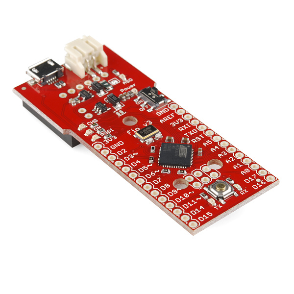
The Fio v3 is a new spin on the Arduino Fio hardware powered by the ATmega32U4. While the Fio v3 is not yet compatible with the Arduino v1.0 IDE, it's still a very capable XBee-ready development board.
The JST-connector and 3.3v system voltage make this a great development tool for portable devices, simply plug in a Li-Poly battery and you're ready to go. Wireless sensor networks and communication are made easy by the on-board XBee socket.
The ATmega32U4, running at 8MHz, makes it possible for you to use the on-board USB jack not only to charge a connected Li-Poly battery but to actually program the device! Because this board uses a similar bootloader to the one on the Pro Micro, you will need to download and install the special software driver below. There's also a board definition add-on for the Arduino IDE which will add support for this board.
- ATmega32U4 running at 8MHz
- Arduino-Compatible Bootloader
- XBee Socket
- Lithium Polymer Battery Compatible
- MCP73831T LiPo Charger
- Reset button
- On/Off Switch
- Status/Charge/RSSI LEDs
Fio v3 - ATmega32U4 Product Help and Resources
Pro Micro & Fio V3 Hookup Guide
November 8, 2013
An overview of the Atmega32U4-based Pro Micro and FioV3, how to install it, and how to use it with Arduino.
Comments
Looking for answers to technical questions?
We welcome your comments and suggestions below. However, if you are looking for solutions to technical questions please see our Technical Assistance page.
Customer Reviews
No reviews yet.
please do not use this to replace the DEV-10116 version.
it removes the most interesting feature of the regular board (wireless programming) and gives me on-board USB programming, which really is not something this board needs (imo at least). Also, having 8 analog inputs is another reason I love the regular Fio.
Anyway. The Fio is my favorite Arduino, and this here, to me, is a downgrade. So please do not consider this as a replacement unit.
I'm betting that wireless programming is going to require a special bootloader on the FIO v3 since the Leonardo bootloader is reset by changing the baud rate on the USB port. If we can force a hardware reset with a cap on DTR like the old FIO then we can probably load code over Serial1 (RXI, TX0). Too bad that cap didn't make it into v3.
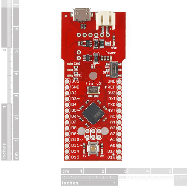
The ATmega32U4 actually has 12 analog inputs, though only 10 are broken out on the FIO v3. A10 and A11 are used for battery level and charge status. The others are shared on digital pins: A6 = D4, A7 = D6, A8 = D9, and A9 = D10.
Also, it will do differential input with a programmable amplifier up to 200x gain. Maybe we can measure thermocouples directly.
Hi, according to the schematic, the battery-level-voltage-divider is before the ON/OFF switch. Wouldn't that cause a permanent discharge of the battery?
Not only is it on all the time, but at 3.6V it's drawing 1.8 mA. With the old FIO + xbee I can get the sleep current down to 0.045 mA. 1.8 mA from this voltage divider would blow that out of the water. They should have used 1M resistors instead of 1K.
Also, on the 328p, once the battery voltage gets close to 3.3V the analog pins aren't accurate anymore, but the chip will still run. The readings start to increase as the voltage falls. However, if you use the internal 1.1V analog reference, then it's still reasonably accurate. But then you'd need probably a 1/5 divider instead of 1/2.
Hi. I accidentally broke the micro usb connector of my fio. When it broke of it ripped the coppertraces of the PCB. So I cant solder it back again(I have tried). So now I cant re-flash it. I compared the connector to my netduino, and that have 4 points (through hole?) tethering the connector. The fio only have 2 smd points. Making it weaker. Hope you can change this in a new revision.
Edit: Managed to solder a spare usb cable to the smd resistors that the data signal goes through, and the 5 volt and gnd breakouts. And it worked :D
Humm... while I was unplugging the cable after reprogramming, I also ripped off the MicroUSB cable !!! I see the PBC plastic support, no copper traces. Please Sparkfun, use a solid thru hole USB connector on next rev!
Could it be possible to reprog using an extre FTDI Basic board ?? or even using an wireless XBee ??
yeah i did the same thing! I can't seem to get xbee programming working either, My theory is that the seperation of Serial(usb) and Serial1(xbee) is a problem for wireless bootloading, to the TXO/RXI pins correspond to the same ftdi as the usb?
Is there a chance we could get a tutorial on how to set this up with Mac and possibly how to get the uploading/communicating with an xbee working?
Thanks!
Be careful when designing a derivative board from this one. The 3v3 rail is connected directly to the VCC input of the ICSP connector.. if you have non 5V tolerant components and your ICSP programmer powers it at 5V, you are up for smoke :-)
To use this with the Arduino 1.0.1 IDE you need to make one change to hardware/arduino/cores/arduino/USBCore.cpp. Replace: PLLCSR = 0x12; // Need 16 MHz xtal With: #if F_CPU == 16000000UL PLLCSR = 0x12; // Need 16 MHz xtal #elif F_CPU == 8000000UL PLLCSR = 0x02; // Need 8 MHz xtal #endif
Otherwise the USB code will try and overclock the board and fail. Oh, and tweak the boards.txt so "build.core=arduino:arduino".
The new USB driver Arduino 1.0.1 brings in for the Leonardo seems to break the old auto-reset-to-program, but I haven't tracked down why yet.
Guys, I just got one of these and spent a good while figuring it out - I was also surprised how little documentation there was. Once you make the quantum leap that it's practically the same as a Pro Micro, that helps a lot as there is a very detailed tutorial available.
Anyway, I wrote up detailed instructions of what I did to get it to work, they are here: [http://forum.sparkfun.com/viewtopic.php?f=32&t=32342]http://forum.sparkfun.com/viewtopic.php?f=32&t=32342
Hope that helps a bit.
Yeah, fail on the hyperlink, but you can copy and paste...
Hi, I am curious about osx support. Do I need some type of driver or should osx find the device out of the box? I have followed the instructions for the pro micro and I can select the device in the arduino ide, however the device does not show up as a serial device in /dev/tty...
I am not able to target the device in any way as osx does not seem to recognize it. I currently do not have access to any linux/windows computers so not sure if I got a faulty device or if i'm doing something wrong. Any pointers are appreciated...
Thanks!
Hello. Please explain exactly where is the jumper SJ2 to be cut to this damn Fio ceased to kill the batteries from overcharging. Is the jumper near ASO LED?
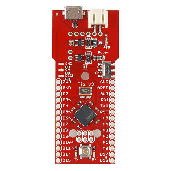
Nope - SJ2 is the solder jumper beside the hole in the middle of the board. The jumper by the ASO LED is SJ1; image showing SJ2 and SJ1
The Arduino Addon should be updated with the new Arduino core files. Not only the patch for the cpu frequency has been incorporated in the main code, but they also solve a nasty bug with the tones function. - Best.
Any chance of getting the part number of the PTC?
Hi to all,
It shall be interesting to mention on the product description page that the USB connector is a MicroUSB (NOT MiniUSB like the Arduino Fio DEV-10116).
Now I need to order that cable and pay again some shipping fees. For now, I'll be unable to recharge the LiPo using this board.
Hi, I think I'm adding a +1 to the comments by asking this, but here goes: Okay, I have the Fio v3 and the Roving Networks RN-XV. I'm on a mac running the Arduino 1.0.1 IDE. I can't seem to get the SoftSerial library to compile when I pick the Frio v3 board. Is there any workaround to this problem? I tried to go to the 0023 release, but then I couldn't find the WiFly drivers or the WiFlyHQ drivers that matched that version. Thanks for any help any of you can provide!
For what it's worth, given that it's some weeks later, I've just got a Fio v3, RN-XV and use a Mac, and after some struggles got it all working in Arduino 1.01 - maybe this will help someone at least. To get the Fio working I dropped the addon/driver bundle into my documents/Arduino/hardware folder, had to edit boards.txt to uncomment some lines to enable 'diskloader' bootloader as that's what mine had come with. This let me choose Fio v3 (Diskloader) as well as Fio v3 (Leonardo) in the boards menu. I downloaded the WiFlyHQ library and dropped that into my documents/Arduino/libraries folder. The secret sauce for getting the WiFlyHQ code samples working was discovering that Leonardo-like hardware connects Serial to the USB-CDC, not to TX/RX, for which it uses Serial1 instead - so it's Serial1 you need to talk to the Xbee/WiFly socket. So edit the WiFlyHQ code samples to do Serial.begin(9600); Serial1.begin(9600); wifly.begin(&Serial1, &Serial); (as well as putting in your own SSID and WPA passphrase) and it all started working.
Why is there no documentation for this? I just bought a this Fio version and now am regretting not getting DEV-10116 so I can actually get it to work. Please don't release unfinished products!
Where do I put the driver files?? I cannot talk to the FIO with the Arduino SDK. Works OK in CodeVision Compiler.
It would be nice if the number of I/O's is stated in the Features for this. Also the differences between this and the previous model. It kind of boring to compare schematics just to spot the differences.
I guess if you get this, there's documentation somewhere that tells you how to use that driver zip folder?
Serial communication does not operate the same as a regular arduino when using the USB. It appears that the Xbee may operate the same as using a USB on a regular arduino but the Xbee Explorer that I received was defective so have been unable to check.
Can you upload sketches wirelessly using this board? That is, can you re-program is, without connecting the USB cable, if the XBee is present, via an established XBee network?
The way that this bootloader works makes that process a little more difficult than in the past. It may be possible but we haven't nailed it down yet.
Thank you, please keep us posted on the progress. The unit looks great (Yeah mounting holes!) But it is hard to reprogram the wireless weather station node via USB when it is enclosed and in the difficult to reach place outside.
If I cut the 5V trace in the charging circuit (SJ2), will I still be able to charge from USB? Or am I then held to higher voltage sources only?
I would like to integrate a 6V solar panel... which can reach higher voltages than the 5.5V listed.
Thanks in advance for any help.