- Home
- Product Categories
- Kits
- FabFM Radio Kit

FabFM Radio Kit
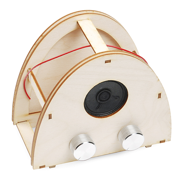
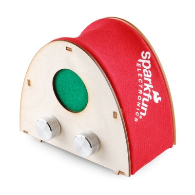
The FabFM is a stylish FM radio kit that you can build with just basic soldering tools! The PCB is all PTH, meaning that even a beginner solderer can put this kit together with a little time. Simply solder the parts in place and you're ready to construct your enclosure. The wooden, laser cut frame doesn't take any tools or glue to put together, each part press-fits into another!
Once you've put everything together, you'll have a fully functioning, old-school style FM radio! The controls are simple: One knob controls the volume of the radio and the other controls the tuning. The controlling firmware is written in Arduino and can be easily modified if you want to tweak the settings (for instance, European customers will want to adjust the band settings) making this kit super hackable!
You can even dress things up a little bit by adding some fabric to the enclosure to cover the electronics, or painting/staining the plywood to showcase the electronics! Check out the Wiki below for more information on building, hacking and modifying your FabFM!
**Note: **This product is a collaboration with David Mellis and Dana Gordon. A portion of each sales goes back to them for product support and continued development.
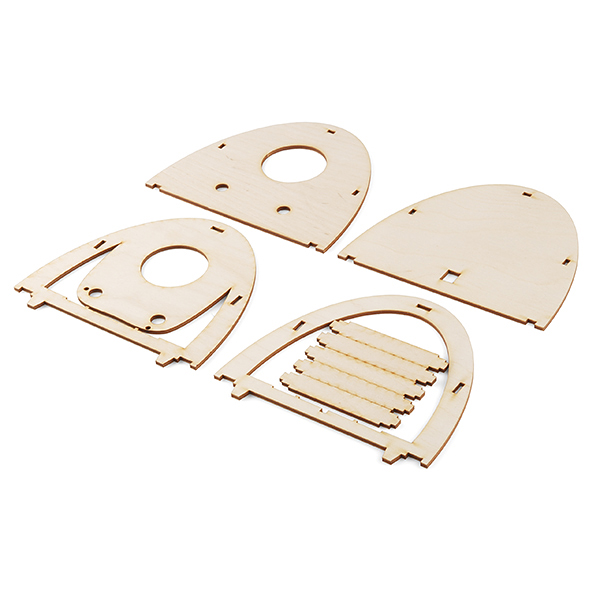
- Laser-Cut Plywood Enclosure
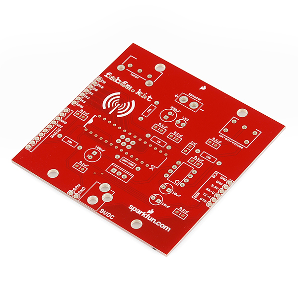
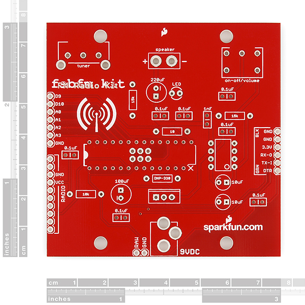
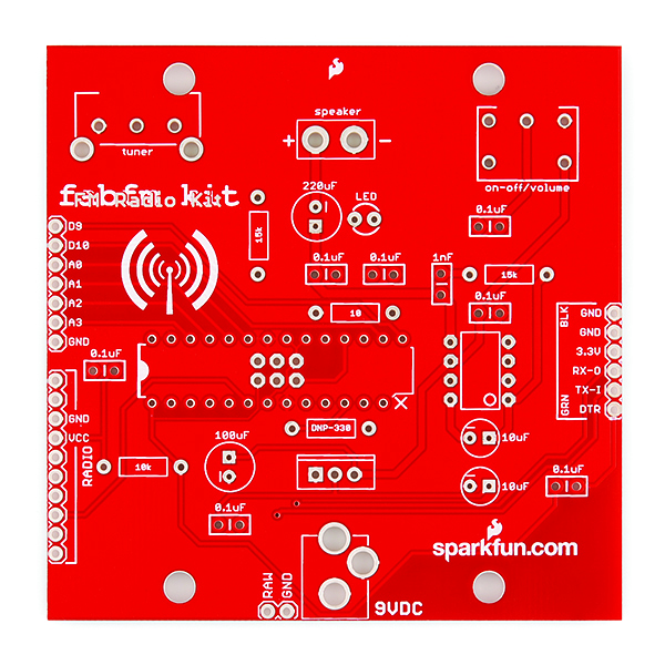
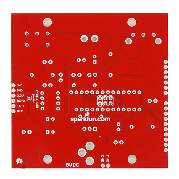
- FabFM Through-Hole PCB
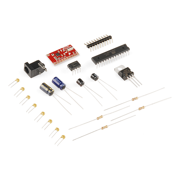
- Pre-Programmed ATMega328
- Si4703 Breakout Board
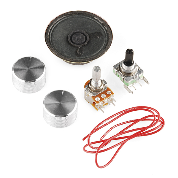
- Potentiometer
- Rotary Encoder
- 2 x Silver Metal Knobs
- 1/2 Watt 8 ohm Speaker
- 2 x 15k Resistors
- 10 ohm Resistor
- 10k Resistor
- 7 x 0.1uF Capacitors
- 220uF Capacitor
- 2 x 10uF Capacitors
- 100uF Capacitor
- LM1117 Voltage Regulator
- LM386N Audio Amplifier
- 10 x Right Angle Male Headers
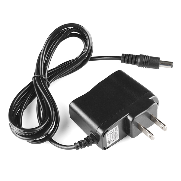
- 9V Wall Wart Power Adapter
- DC Barrel Jack Connector
- 20" Wire Antenna
- Great Beginner's Soldering Kit with All Through-Hole Construction
- Press Fit Enclosure Doesn't Require Tools or Glue
- Designed to be Hacked!
- Open-Source Firmware is Written in Arduino
- FTDI Header On-Board for Easy Programming
- Old-School Style!
FabFM Radio Kit Product Help and Resources
Core Skill: Soldering
This skill defines how difficult the soldering is on a particular product. It might be a couple simple solder joints, or require special reflow tools.
Skill Level: Rookie - The number of pins increases, and you will have to determine polarity of components and some of the components might be a bit trickier or close together. You might need solder wick or flux.
See all skill levels
Core Skill: DIY
Whether it's for assembling a kit, hacking an enclosure, or creating your own parts; the DIY skill is all about knowing how to use tools and the techniques associated with them.
Skill Level: Noob - Basic assembly is required. You may need to provide your own basic tools like a screwdriver, hammer or scissors. Power tools or custom parts are not required. Instructions will be included and easy to follow. Sewing may be required, but only with included patterns.
See all skill levels
Core Skill: Electrical Prototyping
If it requires power, you need to know how much, what all the pins do, and how to hook it up. You may need to reference datasheets, schematics, and know the ins and outs of electronics.
Skill Level: Rookie - You may be required to know a bit more about the component, such as orientation, or how to hook it up, in addition to power requirements. You will need to understand polarized components.
See all skill levels
Comments
Looking for answers to technical questions?
We welcome your comments and suggestions below. However, if you are looking for solutions to technical questions please see our Technical Assistance page.
Customer Reviews
5 out of 5
Based on 2 ratings:
2 of 2 found this helpful:
Fun and good quality... lots of soldering
This was a fun project that I completed with my 10 year old daughter. She loves having her own radio which isn't a digital device (not an ipod or some gadget). I realize that it actually is a digital device but it feels more real. The only thing I would say is that it requires lots of soldering and some of the pins are close together which can be challenging to the novice.
Great Proejct
I assembled this with my 12 year old and it was his first soldering project. Great Project to start with!
What did poor pin 14 ever do to you? PB0 can't be restrained!
14 is the 3rd discrete semiprime and the 3rd member of the discrete semiprime family...so obviously we had to remove it.
Pin 14. Always remember
I just got one of these put together. (I know I'm biased but) This is a phenomenal kit! Easy to put together, took right at an hour. I am very surprised how good the sound is coming from a little 0.5W speaker. Nice work Aaron and David!
+1 for "I know I’m biased but" :)
Very cool. It should be noted that the Si4703 also handles station ID and song info. With a little tinkering, you could add an LCD to display this information.
very true, but since it's not easily broken out, we're not blatantly mentioning it.
Awesome.
You might want to reserve some part of the Wiki page for this to specifically post customer contributed photos of their radios. I bet people will be quite imaginative. Finishing the enclosure needs a lot of thought, it is a complex project all by itself. I'm not a good judge of plywood but it looks like one side of each part is the good face of the plywood and the other side is a little less in finish quality. Nothing bad about it, that is part of how plywood is made. In the case of this project, the person I'm making this for wants really strong colors so the plywood appearance won't matter. It just becomes a canvas. If I were doing this for myself I'd probably stain the plywood...even try to veneer on an exotic wood and then stain that. In fact I would also strongly consider giving the enclosure parts and some cash to a woodworker with instructions to make it pretty.
Paint getting in press fit holes is something I worry about, I am seeing some of that happen with me. I will figure out something. I can probably rasp it lightly if I need to.
Last night I spent a pleasurable 2 or so hours reading two articles by Eric Sternberg on "Basic Wood Radio Cabinet Refinishing". Yes, I understand the FabFM enclosure is not 90 years old. I was looking for techniques for finishing my FabFM enclosure. Sternberg's advice caused me to buy some Deft brand lacquer during my lunch break. I also got a bit wandery with my reading and found and a fascinating site, "Phil's Old Radios" by Philip Nelson ( http://antiqueradio.org/ ). I'm sure there are quite a few other sites out there that discuss how to finish small wood cabinets.
In Finland, this thing doesnt recessary need the firmware update to "European channels", works right out from box. If Radio sounds unclear or sound quality is bad, or station "changes" when you walk past or touch the antenna,remember to CHECK your battery and replace if necessary.
My kit done :)
--- FabFM Video -----
Are the extra pins broken out?
We just got this radio. I hate to be so dumb, but how do you get the Arduino sketch onto the IC chip? We don't see a USB port connector
There's an FTDI header.
I finished my radio. It was tough working with black tee shirt fabric I chose. I think I cut it much too generously (that wasn't too bad -- I cut the excess fabric off) and also the fabric folded on itself in two places on each side of the enclosure frame. I suspect that wasn't good at all. It was very difficult getting the final two plywood "sides" to snap on. At the bottom edge of the radio they would stubbornly pop out of the press-fit holes. Time had run out on me with this project, though: the radio had to be given to my friend. I might possibly have been able to justify an additional delay, the friend would have been gracious about it, but...I wanted it done (impatience on my part.)
I used glue and clamps to get the final two pieces of plywood to stay on. As mentioned in the post above, the right hand knob for the station tuning pot would not install correctly. I'm going to have to find a knob that really fits and looks the same as the ones that came with the radio. Or, replace both knobs with two different knobs.
Another small issue I discovered while working with the enclosure assembly is that there is no silk screening text to identify the pins which were brought out to headers on the bottom surface of the PCB. The ICSP header should be silkscreened too.
Given that I was impatient with the fabric covering part, my final judgement is this kit is not ready for prime time. It has too many small defects that need to be corrected. The "FabFM Radio Kit" silk screening mistake is a bit embarrassing, and it is, to me, a sign of other mistakes with the kit. Removing pin 14 on the "polarization" justification isn't the best way -- that is not the Arduino way or the Creative Commons way.
I think the next time I work on a radio, I want to buy the PCB and circuit components and the actual radio enclosure separately. This has been a very interesting project for me overall, even though I feel this kit needs improvement. I have learned from it.
In the kit that was sent to me, the two knobs are exactly the same. They seem to be engineered to fit the left hand (on/off/volume) pot very nicely, but not the right hand station tuning pot. The right hand pot has a much thicker wiper control than the left hand one. Nothing I did could persuade the knob to fit the right hand pot.
I have a photo archive to share at this location which I hope will help others. Many of the photos are original images taken with my phone and have not been resized. I hope this helps people. Note that some of the photos show how I wired the speaker such that there is a pull-apart connector. I actually soldered the speaker wires on the bottom of the PCB at first. This was a significant mistake. The wires butted against the plywood enclosure. I had to de-solder them and resolder to the top of the PCB, where the speaker wires "+" and "-" hole markings are silkscreened.
I have started assembling the radio into the plywood enclosure. I painted mine with 3 coats of acrylic paint, the Liquitex Basics brand. Acrylic comes off very easily, as I discovered while sanding the plywood and also when squeezing the press fit sections together. I decided against using the Deft lacquer at this time. The main reason is temperatures are still too cold outside for the lacquer to spray on easily and I don't have shop space inside. This is best done outside for me. I don't want to destroy my respiratory system. The "Assembly Guide" does not mention that you need to remove screws and washers from the volume and tuning knobs for later installation. The Guide also does not clearly show you that you need to sister two plywood panels on each side of the enclosure and that it is the sistering of panels on the front (knob side) of the panels that actually holds the speaker into place. The guide clearly needs additional photos to assist the customer in assembling the enclosure. I have taken additional photos of the assembly process that I would like to donate to Sparkfun and anyone interested in seeing them. I am at a bit of a stopping point now because I think I need something that can provide a more controlled "oomph" than my ham-handed ways when trying to get the very top strut to go into the first back panel completely. I am going to go to Lowe's and try to find some clamps that might provide that "oomph" gently without breaking the plywood.
What bootloader is this used with? Can any old stock bootloader be used? Like is this just the standard Optiboot bootloader? Or do I need to compile a custom bootloader and set nonstandard fuses? What specific programmer is needed to burn the bootloader with?
The board comes with a bootloader already burned. All you need to do is select arduino pro 3.3V/8MHz from the menu.
What is the name and version of the specific bootloader being used? Were any fuses changed with respect to the standard fuses for this version? For example did you use Optiboot 4.4 with just the standard fuses?
The bootloader is the same as the one on the Arduino Pro 3.3V/8MHz. Look in the hardware definition files in your arduino install for the specific hex file.
The fuses are different however, since the fabfm doesn't use an external oscillator. This means DO NOT use the burn bootloader command in the Arduino IDE. If you want to burn the bootloader again, just use the hex file in the hardware definitions and leave the fuses.
Thank you! Within the Arduino software directory I could navigate to Contents/Resources/Java/hardware/arduino/bootloaders/atmega and look for ATmegaBOOT_168_atmega328_pro_8MHz.hex and use that. Then set LFUSE=E2 to turn on the internal oscillator? And this is the only fuse change? Then set the lockbit.
Is it crucial to the radio that only an 8 Mhz oscillator be used? Or was the choice made in order to reduce parts count and circuitry? Suppose I breadboarded this circuit. Will the radio work just as well with an external resonator and a "stock" bootloader?
I just bought this for my friend. I do wish the PCB provides for pin 14 of the Atmega and leaves it intact. Many of us have PCB assembly experience. I'll say more once I've built the kit.
I have completed soldering all the components on the PCB. I tested the radio on a friend and she could definitely hear station music and talk in both English and Spanish. She couldn't make out the speech well enough to pin down the station numbers, but she was definite that the FabFM was pulling in radio stations. (If this reads a little strange...I'm deaf, so I have to have others listen for me.) I am still painting the enclosure and that will take a little time to do. I'm very pleased the PCB works when powered up.
I added on every possible header including the ICSP header. I also added an LED and 330R resistor -- the resistor is in the DNP-330 holes. Since the enclosure is not ready yet and I wanted to test the PCB, I wired the speaker wires to a male connector and the corresponding speaker connections on the PCB to a female connector. This way I can literally plug in and unplug the speaker.
The V10 FabFM PCB that was shipped to me needs a lot of improvement. It has silkscreen errors and omissions. The ICSP header isn't labelled. An obvious error like that can be a sign of less obvious errors elsewhere in the PCB. And if this kit is to be truly "newbie-friendly", then you have to pay close attention to the silkscreening. Pin 14 of the Atmega should have been brought out to a through hole on the PCB. Very few if any shops will sell you a kit with IC pins clipped off like this one was and no hole provided for the IC pin on the PCB. Almost every place I know stresses how to orient an IC by locating pin 1 and matching to the silkscreen outline. The Assembly Guide could have done the same. So, in one stroke, I lost an IC pin, the PCB can't take a 28 pin socket without modifying the socket, and I had to pay for the cost of someone snipping off that pin on the IC. I don't know if the PCB was tested with an ICSP header installed. The location of that header is a mistake and it should go elsewhere. It would have been nice to throw in 20 or so right-angle headers in case the user wants to solder them on. The reason I'm bringing this up is because the Assembly Guide says that once the PCB is installed into the enclosure it is going to be very difficult to tske the enclosure apart without damage. So that means someone who decides after the initial soldering work on the PCB to put the D9...GND header on isn't going to be able to do that if the PCB is already in the enclosure. The same logic applies to the other "optional" headers. Or so it seems.
Well per my friend, the radio does work!
Hopefully the enclosure will be able to take the PCB as it is, "fully loaded" with headers.
I am excited and pleased with the kit overall. It allows creative, even innovative, and decorative expression. For example adding a plug in connector for the speaker seems a good step. Decorating the enclosure is a whole area of creative expression itself. I have almost forgotten how interesting it is to work with wood.
I will take some photos of my PCB and point to them with a public DropBox link. Maybe the Assembly Guide can benefit with user-contributed photos like this.
A quick lesson learned today: I should have gotten started with decorative work on the enclosure before I started work on soldering the PCB. I want to paint the enclosure nicely. That takes time to do, I wish I had started it last night. I have the enclosure parts drying now. I am thinking of 3 coats of acrylic paint.
I'm now assembling my kit. Where do I put the resistor for the LED? Is that supposed to go in the DNP-330 holes? The wiki's "modifications" section is unclear on this and I looked at the Eagle schematic to check what might have been intended. Isn't "DNP-330" a bit confusing for a label?
I installed an ICSP header. The location of the header on the PCB is a sad mistake if you don't have a socket for the Atmega. With that location for ICSP, the bottom of the Atmega is going to butt against the tops of the headers where the solder blobs are...even trimmed down solder blobs. This causes the pins of the Atmega to just barely go all the way through their holes some pins are just peeking through the holes on the other side of the PCB. I think I managed to get proper solder connections for all pins of the Atmega but I still have a bit more work to do before I will find out if I missed a pin or otherwise messed up something. I will have more to say late today -- I've still got more soldering to do.
The best reference for assembly is the assembly guide. See the Note at the end of Step 1 for info on the LED. Also, use the image of the assembled board to make sure you are putting everything in the correct spot.
The DNP-330 (Do Not Populate) and the LED are not included. If you want an LED with your kit, you will need to purchase and install those separately.
Also, the ICSP header is not intended to be soldered to (although you can if need be). The atmega has an arduino bootloader, so you can load code over the serial port, the ICSP port is not needed.
Hope that helps!
I assure you that I am following the assembly guide at every step. I also check the Eagle board layout and the schematic. What I report here is reflective of following the assembly guide. As far as I can tell, there is not one single image available showing an LED installed on the PCB...or the required resistor.
Perhaps my question was unclear: does the resistor have to be installed in the holes for the DNP-330? It might be good to have a photo showing the PCB with an LED installed. If you look at the V10 PCB, you'll also see that the PCB doesn't indicate the polarity of the LED, e.g. where should the flat side go? The Eagle board file for the V11 LED holes does seem to suggest the flat side is pointing to the left.
Do you have any images showing installation of a recommended ICSP header? I'm stressing the word "recommended" because perhaps your idea of header is a great deal different from my implementation: I just put in six standard straight pins in sets of two, following what the silkscreen suggests. The PCB doesn't even label the header area. If you say that a header shouldn't be installed there, then perhaps the assembly guide should have a section discussing this.
Does the resistor have to be installed in the holes for the DNP-330?
Yes. The resistor needs to be installed for the LED to work. I understand how the DNP label can be confusing. We'll get that off of there on the next rev.
I'd like this to be STEREO and have some options to be a decent alarm clock, by adding an RTC, LED time display and LCD character display for setup. Or hex LED display for that.
Is it possible for someone living on the USA East Coast to be able to pick up stations in Guatemala or El Salvador with this kit? I would like to make this as a gift to a dear friend.
No, typical radio broadcast FM stations are around 100Mhz, which is mostly line of sight. Yes there are ways to get farther but nothing dependable (unless you can control the troposphere).
Of course, you can program the radio to work when you're in other countries if you know the broadcast details (pre-emphasis etc).
Why not an Arduino One version of this project ? most people have parts already lying around, can the same sketch be used ?
I guess it was a question of cost. You can buy an Arduino for $25 - $30, but you can just get the chip ATmega328 for less than $2. They could have made a shield or just put everything on one board - the number of soldering points are probably similar. SparkFun: pretty please with sugar on top - put some IC sockets in your kits!
I accidentally edited/deleted your comment with my response and I can't get it back, sorry about that.
Also, the fabfm example sketch should work with the arduino uno (don't you mean uno?), just be sure to select the uno as your hardware.
What is the rotary encoder used? Does SparkFun stock it? I have been unable to find a decent simple panel mount rotary encoder.
A decent panel mount encoder is the ALPS EC12E2420801, Mouser p/n 688-EC12E2420801, 24 detents, less than $1 each. The Sparkfun friction fit plastic knobs don't work very well with the plastic shafts like these encoders have; a knob with a set screw is better.
What's the deal with pin 14 of the AtMega328 (which is PB0)? The PCB layout omits that pin.
polarization, so you knuckleheads don't put it in the wrong way ;)
Or you could just use a socket and leave that poor pin alive...
The labels "fabFM-Kit" and "FM Radio kit" in the silkscreen (photo 3) seem to overlap. Is that on purpose?
That's a limited edition 2-D hologram/silk mistake.
I got the limited edition ....yaaaa :)
Haha
70$ for a simple radio? Sorry I can't justify the cost.
This is a nicely engineered piece of hardware, but i must agree. A few years ago, when building something like this from scratch would have been quite a challenge for me, I would have been very excited about this product, but still not $70 (+VAT 24%) interested.
24% VAT?!?!?! Geeze, and I was whining about ~8% Colorado sales tax.... My deepest sympathies
Is the Atmel chip pre-programmed? What is needed to program it or re-program it?
Also, I see a hex file at github; is actual source code provided or is this closed source?
It's pre-programmed. We will very specifically mention if you need to program a kit. this one comes with everything you need. we're posting a full assembly video today that shows how it goes together. we just include the source code so you can modify it if you want.
Almost forgot - under the Atmel chip is a 3x2 connector. This is a regular small ICP header - so any Atmel programmer will do!
Thanks! I didn't find the .ino file but did see the button for a zip file of things that included the .ino file.
I see a file fabFM-Kit/firmware/fabfm/fabfm.ino in the repository. This is a source file for the Arduino programming environment. On the right side of the PCB (top silk up orientated so you can read the text) is a line of 6 pins for an FTDI adapter or cable which can be used from the Arduino programming environment.