- Home
- Product Categories
- 900MHz
- XBee-Pro 900 XSC S3B Wire

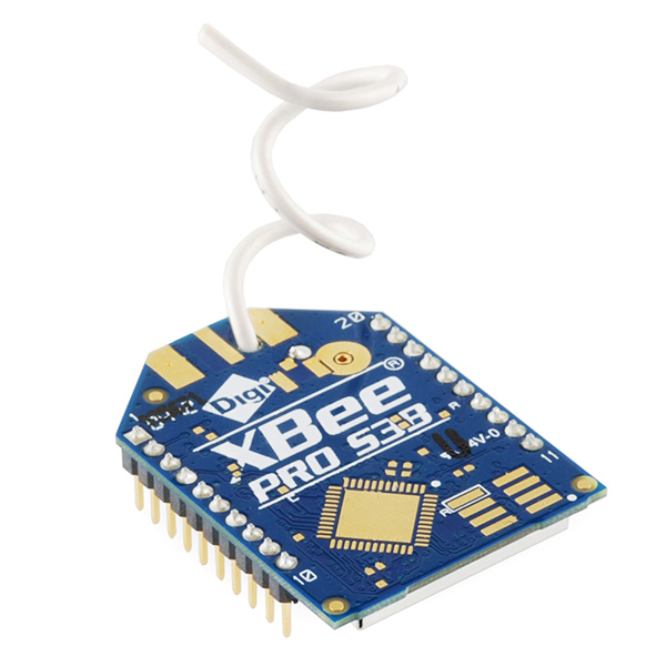
XBee-Pro 900 XSC S3B Wire
Do you need 'moar power' for your wireless widget? The XBee-PRO XSC 900 MHz RF module features two times the throughput and 20 times less current draw than the previous XSC module. This version (S3B) features an ADF7023 transceiver from Analog Devices, which can toss your data up to 28 miles Line-of-Sight (LOS), along with low power consumption, drawing less than 2.5 uA in power down.
Also, the latest XBee-PRO XSC is firmware compatible with the legacy 9XStream® and the legacy XBee-PRO XSC modules. And because it's an XBee RF device it is, of course, pin compatible with existing through-hole XBee modules.
Not sure which XBee module or accessory is right for you? Check out our XBee Buying Guide!
Note: This module does not work properly with anything connected to the RSSI pin. Our current XBee Explorer USB and XBee Explorer Dongle have a solder jumper on them to let you disconnect the RSSI led.
Note: Due to manufacturer's restrictions in other countries, we can only ship these to the USA and Canada. Sorry world!
Replaces:WRL-09085
- Analog Devices ADF7023 Transceiver, Cortex-M3 EFM32G230 @ 28 MHz
- 902 MHz to 928 MHz Frequency Band
- 10 Kbps or 20 Kbps Data Rate
- Up to 2000 ft (610 m) Indoor/Urban Range
- Up to 9 mi (14 km) LOS w/ Dipole Antenna
- Up to 28 mi (45 km) LOS w/ High-Gain Antenna
- Up to 24 dBm (250 mW) Tx Power (Software Selectable)
- Voltage Requirement: 2.4 to 3.6 VDC
- Tx Current: 215 mA
- Rx Current: 26 mA
- Sleep Current: 2.5 uA
- Wire Antenna
XBee-Pro 900 XSC S3B Wire Product Help and Resources
Exploring XBees and XCTU
March 12, 2015
How to set up an XBee using your computer, the X-CTU software, and an XBee Explorer interface board.
2 of 2 found this helpful:
Special Pinout Considerations
This board is unique in the XBee family because it has a slightly different pinout. For standard pass-through uses, this board can be mounted to one of our XBee regulator boards with a small adjustment. You will need either the dongle or the explorer to make the needed adjustment easily. Locate the RSSI jumper on the back, and cut the trace between the pads with a small knife.
Core Skill: Programming
If a board needs code or communicates somehow, you're going to need to know how to program or interface with it. The programming skill is all about communication and code.
Skill Level: Rookie - You will need a better fundamental understand of what code is, and how it works. You will be using beginner-level software and development tools like Arduino. You will be dealing directly with code, but numerous examples and libraries are available. Sensors or shields will communicate with serial or TTL.
See all skill levels
Comments
Looking for answers to technical questions?
We welcome your comments and suggestions below. However, if you are looking for solutions to technical questions please see our Technical Assistance page.
Customer Reviews
No reviews yet.
This whole "modifying the explorer boards to get things to work" thing sounds really sketchy to me. I just got a set of XBees like this and was thinking of getting a usb explorer for it. Do the modifications actually fix things? Also, the product description says there is a solder jumper but some of the comments talk about removing a resistor, what specifically needs to be done in order to get things working?
This module uses what is on all other modules the RSSI pin for a different purpose. Because of this there has traditionally been an LED on the board to view the RSSI status. Unfortunately the resistor/LED will cause problems on this module if they are hooked up to this pin (I don't remember all the details). Originally people were just removing the resistor to get things to work, but in the latest revision we added a solder jumper to make it easier to use with this module. Because the RSSI light is such a useful feature and it works fine on most modules we didn't want to completely remove it, but we wanted to find an easy way to make the Explorer boards work with this module. Hope this answers your questions.
I think that clear up things. I have had the chance to do some of my own research and stumbled upon something in the XBee manual. Here is an excerpt from page 77:
I checked the schematic for the explorer and it also reads RSSI info from pin 6. Is it possible that this issue is because RSSI is not enabled by default? Would everything work without modification once RSSI is enabled?
Check out this forum post which gives a much better explanation of the issue. The resistor and diode actually pull the pin low causing the module to go into a different state on power up.
How can I attach an antenna with it ?
This should come with an antenna connected. If you are looking to use your own antenna you'll want to check out the u.FL or SMA versions.
I need to connect a Dipole/high gain antenna with it. and I don't any version of this product with a connector
It looks like this is the only version of this XBee that we carry as they are not very popular. Try checking with Digi, they should make a version that you can add your own antenna to. Good luck on your hunt, sorry we can't be of more help.
How will I search for a high gain antenna for this ? what are the keywords ? Would a 2.4 Ghz Antenna work ? or I would need to search for a GSM antenna ?
No, this is a 900MHz device. I would check out the datasheet for the modules, it should actually lists some tested antennas near the back.
my required is transmitted data for 5 km (AIR TO GROUND), the data rate around 6000 bps, can S3B achieve it? how much gains antenna should i use. thanks
Can someone explain me the difference between the firmwares? I'm seeing XBP9B-DM, XBP9B-DP and XBP9B-XC. The standard 5v sparkfun FTDI adapter doesn't work without flipping RX/TX pins, so once i do that i can recover the modules and it shows up on XTCU without modifying pins. The modules see eachother but i can't get serial communications through (using it for telemetry on a pixhawk uav). When i flash the XC firmware, i get nothing on XTCU, basically doesn't show up.
What firmware should I use for just a P2P link on these modules?
Also if i need to remove the rssi led from the explorer board, do i need to do the same with others? I also have a UARTSbee adapter from seedstudio. Does that mean all xbee compatible boards need to be modified to work with this module?
XBee-Pro 900 XSC S3B Wire Defaults as of 3/28/2016 if you ever brick your XBee:
Product Family: XBP9B-XC
Function Set: XBee Pro XSC (S3B) 9600
Firmware Version: 3011
Can I use this with the Fio V3?
Is this module compatible with the current XBee library for Arduino? The Library page says it is compatible with Series 1 & 2. However, I'd like to know if this counts as one of those series.
Is the arduino library compatible with S3B?
I'm not sure, however, I should be able to let you know in a week or two if you are still wondering... Also I used a library built for the Xbee Series 2 on a Xbee-PRO XSC, so my thinking is that yes you can use the Arduino Library. ^_^
Feel free to checkout my blog which has the exact equipment, setup, libraries and code I used on a Weather Balloon last year: http://rocketmanendeavours.blogspot.com/2015/03/weather-balloon.html
Is the arduino library comaptible with S3B??
is this compatible with ArduIMU?
If I have this module (w/ wire antenna) and a module w/ dipole antenna at the base station, Will I get 9mi LOS range? or should I have dipole antenna at both side?
Probably not. The features list states "Up to 9 mi (14 km) LOS w/ Dipole Antenna” This assumes perfect propagation of the signals. A long antenna has a different radiation pattern than a dipole and as a result, a long wire will have less gain than a dipole. You will likely see a useful range that is considerably less than 9 miles. Additionally, both styles of antenna have null areas where little signal is emitted. If your devices are aligned such that each is in the null of the others radiation pattern, you will see much much less than the ideal range. To further muck things up, if one antenna is aligned horizontally and the other is aligned vertically, they will be out of phase with each other and signal reception will be further degraded. That said, a dipole is not difficult to construct for the frequencies involved.. Give it a shot and see what happens. You can also install a long wire on your field module and a high gain directional on your base station. If you can track your field module with the high gain antenna (something you will probably have to do with the dipole anyway) you can probably expect better results. Visit the A.R.R.L. website for a truckload of antenna information.
What is the range of this thing with the provided wire antenna? This page claims "Up to 28mi w/ High-Gain Antenna". What does this antenna count as?
If the picture above is any indication, it is a helically wound, end fed wire antenna. This is not a "High-Gain Antenna".
Where and how can you get the "High-Gain Antenna".
if you want to buy one, your looking for something like a wifi ap antenna. Or you can roll your own for a few cents. The thing to remember is radio propagation is a zero sum game. you can have a low gain antenna that sends signal in all directions or a high gain antenna that only sends and receives signals from the direction the antenna is pointed.
I am trying to configure this with X-CTU, but when trying to read the "modem parameter and firmware" X-CTU says that "the modem configuration file is not found." Updating does not fix the problem. I did remove the RSSI LED from the sparkfun explorer board and it works fine with other Xbees, series 1, series 2, and pro versions.
Should I use XBP09-XSC?
As noted in the comments, plugging this module into an XBee Explorer module will cause X-CTU to lock up when trying to communicate with it. I unsoldered the RSSI resistor (broke off a solder pad in the process) to make it work. It seems "And because it's an XBee RF device it is, of course, pin compatible with existing through-hole XBee modules." isn't entirely true.
Was just about to quote the same line.
This board does not work with the standard adapter boards,as there is a pin change. This should have been made clear on this product page, would have saved me an hour of frustration. You have to modify the adapter board. Specifically, you have to physically remove the RSSI LED or the R4 resistor from the standard adapter board. The XSC has a different pinout compared to a normal XBee and this LED will drive the config pin low and cause the module to be unresponsive. See this thread: https://forum.sparkfun.com/viewtopic.php?f=13&t=33274
I apologize for this, we did not realize that they had modified the function of the RSSI pin making it not compatible. I will get the description updated and hopefully we will have a new board out soon that is compatible.
Yes, a new board for these would be good. :)
Also, do you know anything about a different command set for this module - it appears the ATD1, ATD2 etc does not work ? Thanks, Rick
Hi
what is better antenna to this?
I was on the beta test for these last year and fell in love! Just yesterday I did some testing (Ublox + UF.L S3B) and was able to get about a 1 mile radius at ground level in a suburban environment (small city, largely residential, rolling hills, little vegetation due to season).
I am actually using these in a production product and can't speak highly enough of this line. I bought my original XSC models for a drone and liked them... adding mesh to the lineup with these is an incredible upgrade.
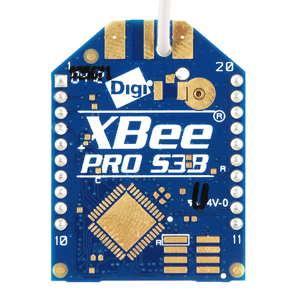
Also, for those who really care... the S3B does not have an IC on the top of the board (the photo is an old XSC), though there is a pad there for it. The documentation exists through Digi to determine which chip they plan of having put there, but during the beta we were advised that there are other components missing from the board to make the IC functional (stated but I can neither confirm or deny). The IC is a Freescale MC9S08QE32 that is supposed to ship with an Eclipse IDE.
900MHz does have less attenuation per "mile" than 2.4GHz, for sure. Laws of physics. And the "B" model radio does say it has up to 250mW transmitter power. Lots more than typical 2.4GHz products. In the US, FCC regulations restrict the transmitter on-time (duty cycle) in this band, in a complicated combination of data rate/bandwidth and duty cycle. Products that use frequency hopping are allowed higher duty cycle/bandwidth. These radios do use frequency hopping spread spectrum. Amazing for the cost.
But 28 miles, even with the required high gain antennas for that line of sight range - is a marketing stretch. You might get that with a 9dBi yagi (big antenna) and with both ends elevated to clear the "Fresnel" zone for that long distance.
But for sure, 100mW or (the cheaper one) at 900MHz with modest antennas and some non-LOS is a good thing for range well beyond what 2.4GHz can do.
This 902-928MHz band is No. America only. I don't think the EU (ETSI) has anything comparable - their 868MHz unlicensed is not enough spectrum to do FHSS like the 902-928MHz band.
The 902-928MHz band, in the US, has lots of "SCADA" users in it, but that's very low duty cycle.
I used two Xbee-PRO XSC and two duck antennas and received signal way over 28 miles away on a weather balloon. However, I'm not sure how well the wire antenna would work compared to my duck antenna.