- Home
- T'Rex Robot/Motor Controller

T'Rex Robot/Motor Controller
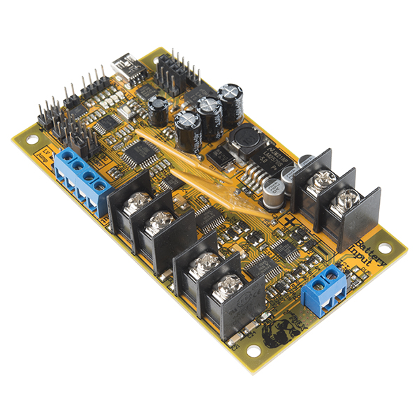
T'Rex doesn't want to be fed, he wants to hunt! The T’Rex controller from DAGU is an Arduino compatible robot controller designed to power and control servos and brushed motors. This controller combines an Arduino development board with a dual FET H-bridge motor driver. The heart of the board is an ATMega328P AVR microcontroller which comes loaded with the Arduino bootloader and some simple control code. The code on each T'Rex controller can be easily accessed and changed in the Arduino IDE using the built in USB interface, ISP, or FTDI sockets.
The T’REX controller is rated for a maximum voltage of 30V and can handle currents in excess of 40A per motor. A set of screw terminals are provided for the battery connection as well as for connecting motor outputs. The Dual H bridges are rated for stall currents of 40A per motor and average currents of 18A per motor. Factory calibrated hall-effect sensors measure current draw of each motor. Each motor has independent variable electronic braking. Self-resetting PTC fuses prevent damage from stalled motors. This board is ready to go out-of-the-box! The supplied code will accept input from a standard RC vehicle receiver and handle the "mixing" for differential steering. If you would rather control it with BlueTooth or I2C input, that can be done simply by downloading the proper Arduino sketch, providing an optional BlueTooth dongle, and/or changing a few constants. Also, because it is an Arduino compatible controller, feel free to write your own control scheme or even load it up with sensors and go autonomous! Uploading code is as simple as selecting "Arduino Nano w/ 328" under the boards menu in the Arduino IDE.
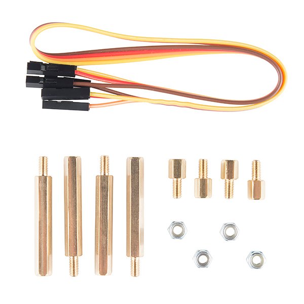
Note: Included with the T'REX controller are 4x 30mm and 4x 6mm brass hex spacers. When mounting in the Wild Thumper these spacers need to be joined together to make 4x 36mm spacers. This will hold the PCB high enough to prevent any short circuit.
- 1x T'Rex Robot/Motor Controller
- 4x 30mm Brass Hex Spacer
- 4x 6mm Brass Hex Spacer
- 4x Hex Nut
- 1x 4-wire Female to Female Cable
- 6V -30V operation with built in solid state power switch
- Programmable with the Arduino IDE (ATMega328P, 5V @ 16MHz)
- Dual FET "H" bridge rated 18A with self resetting PTC fuses
- Electronic braking and current monitoring for each motor
- 3-axis accelerometer provides angle and impact detection
- Auto-detects RC, BlueTooth, or I2C control
- Voltage translation on I2C interface
- 6x Servo Outputs
- 4.33" x 2.4" x 1"
- [User Manual](https://cdn.sparkfun.com/datasheets/Robotics/T'REX robot controller instruction manual1.pdf)
- Example Code
- I2C Example Code
- [Android App](https://cdn.sparkfun.com/datasheets/Robotics/TREX V2.3.apk) (BlueTooth module required)
- Product Video
T'Rex Robot/Motor Controller Product Help and Resources
Core Skill: Robotics
This skill concerns mechanical and robotics knowledge. You may need to know how mechanical parts interact, how motors work, or how to use motor drivers and controllers.
Skill Level: Competent - You may need an understanding of servo motors and how to drive them. Additionally, you may need some fundamental understanding of motor controllers.
See all skill levels
Core Skill: DIY
Whether it's for assembling a kit, hacking an enclosure, or creating your own parts; the DIY skill is all about knowing how to use tools and the techniques associated with them.
Skill Level: Noob - Basic assembly is required. You may need to provide your own basic tools like a screwdriver, hammer or scissors. Power tools or custom parts are not required. Instructions will be included and easy to follow. Sewing may be required, but only with included patterns.
See all skill levels
Core Skill: Programming
If a board needs code or communicates somehow, you're going to need to know how to program or interface with it. The programming skill is all about communication and code.
Skill Level: Competent - The toolchain for programming is a bit more complex and will examples may not be explicitly provided for you. You will be required to have a fundamental knowledge of programming and be required to provide your own code. You may need to modify existing libraries or code to work with your specific hardware. Sensor and hardware interfaces will be SPI or I2C.
See all skill levels
Core Skill: Electrical Prototyping
If it requires power, you need to know how much, what all the pins do, and how to hook it up. You may need to reference datasheets, schematics, and know the ins and outs of electronics.
Skill Level: Competent - You will be required to reference a datasheet or schematic to know how to use a component. Your knowledge of a datasheet will only require basic features like power requirements, pinouts, or communications type. Also, you may need a power supply that?s greater than 12V or more than 1A worth of current.
See all skill levels
Comments
Looking for answers to technical questions?
We welcome your comments and suggestions below. However, if you are looking for solutions to technical questions please see our Technical Assistance page.
Customer Reviews
4 out of 5
Based on 3 ratings:
0 of 1 found this helpful:
Brushless conversion
I wanted to make a self driven ROV. The DC motors of the TRex are not up to the job, as there is nearly no low speed control. Also very few 12V DC motor controllers out there. Now trying to replace the motor with a brushless motor, so I can use an off the shelf ESC. Not the controllers fault.... but it would be nice if the TRex could have a brushless motor-gearbox alternative.
works fine so far
So far it works great. I need to figure out if the low voltage shut off can be turned off.
great motor controller
It took some tinkering but once I got it working it works great. For me there was a problem with the IIC address. It will store a new one in EEPROM if different than 7 and somehow I changed it. After I removed that check in the program for the controller there have been no more problems.
After much frustration and searching, I have found the correct drivers for this board. They can be found here: http://www.silabs.com/products/mcu/pages/usbtouartbridgevcpdrivers.aspx
Have to say, while this board looks great, not impressed. I have had 2, the first showed up dead, and the second died after minimal use in a Wild Thumper (well below the rated limits).
So far Sparkfun has been great about returns, but I am moving on to something else (http://www.pololu.com/product/1112/).
I have a T'Rex motor controller on a Wild Thumper Chassis. My first time running it in RC mode I shut off the RC transmitter to avoid stalling the motors in a mishap. (I'm a total noob when it comes to RC and Robots.) Anyway, when I tried to turn things back on, both left and right motor fault led's were on and of course there was no power to the motors. What do the fault led's mean and how can I clear the fault.
Hmm... on this product, it says it replaces ROB-11057, but when you click on the link, it brings up this exact page.
I think they're still playing with the "Previous Versions" box to the right of the product description - you'll find the correct link to go to an older version (without the redirect) there :)
I want to buy a T’REX controller,but it had Retired,where can I get it?
I'm on my second one of these boards. I got one new from sparkfun and it ran for a minute or two then the two fault lights went on and they will not go off. Tried changing batteries and so on. I asked for a RMA but sparkfun's technical is anything but helpful. They made the RMA for the wrong item. Additionally it takes so long for them to respond to messages that I had time to order a second card from another site. Maybe sometime sparkfun will get their support right. The next board I received ran for a couple minutes and now its completely dead no lights or anything. At least the other site's support is more responsive and helpful. Avoid this board in my opinion.
Всем привет! в свое время я тоже приобрел эту плату, и столкнулся с рядом проблем, к сожалению ответов на свои вопросы я не нашел и долго разбирался перед тем как запустить свое устройство. Решил поделиться своим опытом: прежде всего скажу что плата мне очень понравилась, сочетает в себе все что нужно! по оптимальной цене. но есть нюансы: 1. для питания нужен хорошие аккумуляторы. простые батарейки подойдут! 2. при подключении блютус модуля HC-06, нельзя его просто вставить в разъем, необходимо проводами подсоединить так чтобы TX соединился с RX а RX с TX. 3. в комплекте с платой идет программное обеспечение. приложение для андроида и ардуино скетч. как я с ними не пытался запустить машину, ничего путного не вышло, машина двигалась с рывками, в конвульсиях. вот история моего проекта http://roboforum.ru/forum10/topic14711.html?sid=0b46720d88e69be644eefc3b68d184f9
там можно почитать мои ошибки, на последних страницах увидеть результаты.
Hi Sirs!!!! Yesterday I recieved the T'rex controller, now I'm waiting for Wild thumper 6WD. I'm testing I2C comunication with an arduino board without motors but always appears the motor fault (obuislly). I'm thinking to connect two resistor (one in each channel) of 10K to eliminate this faul, what do you think about?
Some days ago I contacted with Dagu to request the schematic and the eagle files for T'rex controller board, but they never answered me, there's any person who have this schematics?
Finally I will supply the T'rex controller with 2S Li-po battery, wich when is fully charged the voltage is 7,8V. Maximum voltage range for Wild Thumper motors is 7,5V, I need to limit the PWM signal to limit the voltage motors to 7,5V?
Thanks in advance.
I just have to say that while I understand that examples and tutorials will not be explicitly provided for you with this board, (and I do applaud Sparkfun for being so honest about that) this board is almost impossible for me to take control over. I have so far tried taking control with the board itself, but the example coding that comes with it will not compile because of a coding error, and this sketch is so complex nooby me doesn't have any idea how to fix that. I then moved on to trying I2C with an arduino uno. I used the example coding (specifically "I2C tester") and that worked out well on the side of the arduino. That's about where the working part ends, however, because the board will never actually send back the status data packet that it is supposed to use. Again I figured this was a coding issue, and again I could not dig deep enough into the sketch without a headache to find the issue. Keep in mind I have been doing this for only about a year, and I have no formal coding training of any sorts, so this could just be my incompetence towards this... not sure...
My point is, does anyone know how to actually take control over this board to make it work? I would love any help at all, but more specifically does anyone know of a sketch that actually allows for control over I2C?
This product is working OK for me on a 6 wheel Wild Thumper chassis, all except for the accelerometer outputs. All three axes read about 720 decimal no matter what orientation I put the board in. Anybody else have this experience, or know what I might check to try a fix?
Answer to my own question: The Accelerometer.ino file has
Changing to
fixes the problem
Does anyone have any ideas as to which battery would be best for this? I'm not great at picking batteries and I have no idea which to pick. Any help is much appreciated.
Anyone able to compile the example code for this board? This board seems to have an issue with reading the accelerometer over I2C as for all axis (x, y, z) it reads the pin for the x-axis. I've sent an email to Sparkfun tech support but have not yet heard back. Any help would be appreciated.
I have an issue with this board. I built a chassis for 4 motors (6V, stall current 2.2A) and I'm driving them with the controller (left side = 1 channel, right side = 1 channel). The power source is a Li-Ion battery 7.2V, 6600mAH. The issue is that when the current goes over 4-4.5A the controller goes down. Any hints? I looked in the code and there was nothing that did that.
Thanks
Sorin
It is possible use this board to control wheelchair? Each motor have 250W and supply at 24 Volts
I believe that this board will power the motors. 24V at 250w is a hair over 10 amps per motor. The TRex has 18 amp per motor with up to 40 amps stall. If my initial tests go well, I will be using this board to control wheelchair motors at around your power.
I'm curious what you're doing? I'm going to be making a large overpowered, somewhat dangerous robot for use in the house.
Hi!
I'm working with a different type of bluetooth, not the Bluetooth Gold Mate, i'm using HC-06, Do I have to change the program previously charged? Please I really need help
Has anyone tried controlling this via I2C on a raspberry pi? I'm trying but coming up short.
i try to work with trex but nothing work i connect the Bluetooth and the android program recognize the Bluetooth but nothing work i try to upload the code again it upload and nothing work. is power switch has to be connected or what plz i need help the supply is 24 v 10 amp
Has anyone tried to use the analog pins A4 and A5 to read voltages? I have a joystick that I want to connect up to the T rex, and use A4 and A5 to read the voltages (1-4V) from the joystick position in x and y. I tried turning off the internal pull up resistors using this guide:
http://panasonic.mironto.sk/testing/pullups/
I commented out the following in wire.h // activate internal pullups for twi. // digitalWrite(SDA, 1); // digitalWrite(SCL, 1);
I'm still reading 5V on both SCL and SDA lines.
Thanks Chris
Hi
I made next, retire all component if you want read ADC4, Components R33, QM1 and R35 and link the PIN SDA with pad QM1. Obviously you cant manage I2C, but you can read one potentiometer o read anything with ADC.
Regards
I am using the Wild Thumper and finally got all the bugs worked out, and found it had been replaced with this controller. I have not used the new board and I will most likely not use the new board. I figured I'd explain why.
At first glance I had hoped that the problems that plagued me with the Wild thumper had been taken care of, but after reading comments and looking through the specs, I'm skeptical whether this board is a proper upgrade. Compared to the complains in the comments on the Wild Thumper, the T'Rex appears to be more delicate. There are a long list of motor failures listing the same issues. To be fair, after a quick glance at the supplied code it doesn't appear that the current sensing is being used in-code to limit the motors as the code does on the Wild Thumper. The only referances I can find are for reading the current and supplying a value in mA for testing and communications. As such it appears to be relying on the speed of the resettable fuse to protect the motors and not limiting the amount of control signal transient to the controller, effectively allowing the motor to be able to be switched on hard fairly quickly. I would suggest that anyone who uses this board go over the code very carefully and add in the current limiting code from the Wild Thumper at the very least, if not come up with something better. Since, for me, all links on this site redirect to this board (including the "previous versions" link), here's the link I found to the board: https://www.sparkfun.com/products/retired/11057 I'd say to get the code soon, it's getting hard to find documentation for that board. Nonetheless, the motor controller does not look appealing after dealing with the issues I had on the Wild Thumper (bad soldering, and one controller would intermittently cut out for no apparent reason)
In my opinion, the T'Rex might be a great board for someone who has a skid-steer RC that might want to augment it with an arm or collision sensing, but as for the ability to add sensors and other useful robotic devices, this board is starved for available I/O. There are only 2 accessible Analog inputs (via I2C connector) versus the Wild Thumper's 5, and there are less Digital I/O. I had to cut my project back due to lack of available I/O already, and lost features to squeeze everything I could out of the board. I can't use this board as a pure robotic controller. (1 servo, 5 IR reflectance sensors, 4 remote control inputs, 2 mode selection switches and so on, on , I don't have a list in front of me).
I'm glad there's a strong motor controller available, but for my purposes it's not quite a direct replacement for the Wild Thumper.
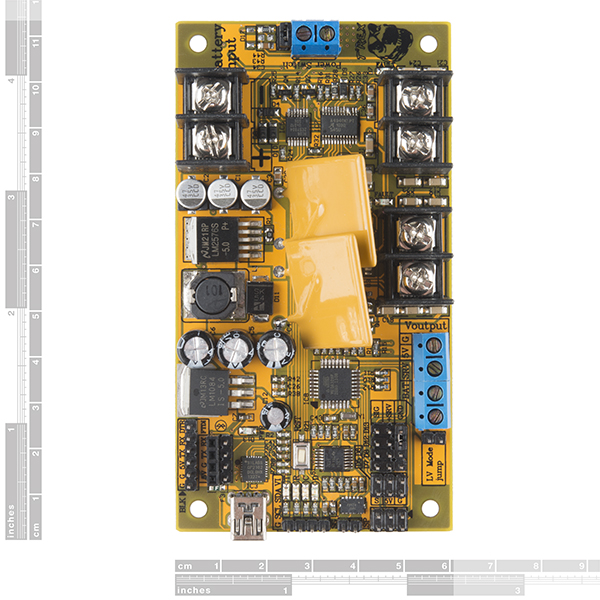
I'm setting up this board for use with I2c from my UNO, and the manual shows the connections as being GND, SDA, SCL, and +Vi. What is "+Vi"? I'm assuming it's the logic voltage of the master(5v) but I want to be sure!
+Vi (+V input) needs to be the logic voltage used by the external controller. It can be from 1.8V to 5V and is used for the pullup resistors to the external logic. This allows any other controller to control the T'REX regardless what voltage it runs at.
Hi, I put this board into the wild thumper and controlled it using a radio just to try it out. It was awesome for about 2 minutes. I ran it over a shoe and the fuses tripped after a few seconds of trying to get over the troublesome obstacle. Since then all it does is make an audible hum and the motor fault lights come on. I combed through the board looking for damaged components and found one of the caps next to the motor connecting had basically broke in half. I replaced the cap and still had the same issue. I hit the throttle and it goes nowhere. I figure it's not the fuses since the fault lights are coming on and the board is humming when I hit the throttle. Is there anything I should check?
-sad nerdy toy enthusiast
please contact tech support. they might be able to help you out.
Hi, I have questions about the IO pins;
I used the io pins definition from the sample code, and tried to power the left motor with the following codes: digitalWrite(lmdirpin,1); // drive left motor forward digitalWrite(lmpwmpin,1); // left motor at 100%
however, what I found is that I actually got potential difference on the right motor output channels
similarly, when I tried to power the right motor, I got potential difference on left motor output
OMMMERRGAAAHHH!!!
I was writing that same code and messing around for like an hour thinking I must be an idiot, looking at the drawing, yep left motor, power in yep, but why motor no turny? Read your comment and confirmed, they have it labeled wrong in the sample code.
Hi, I've got some problems with this controller, I've changed the code for the bluetooth to be compatible with the BlueSMiRF Silver (WRL-10269), connected to the Wild Thumper 6WD (ROB-11056) then connected a 7.4V LiPo (PRT-10471) to the controller. I get the correct beeps for the mode 2, but when I pair with the Android app the motors start to glitch, and the controller resets if I try to drive them with the app.
I ran the diagnostic mode on the controller (just the controller, no battery, BT nor motors) and got these results (excerpt):
Battery voltage: 425 X: 504 Y: 639 Z: 637 Lmotor current: -48mA Rmotor current: 48mA PWM:240
Battery voltage: 425 X: 499 Y: 638 Z: 636 Lmotor current: -48mA Rmotor current: 48mA PWM:245
Battery voltage: 425 X: 500 Y: 640 Z: 638 Lmotor current: -48mA Rmotor current: 0mA PWM:250
Battery voltage: 437 X: 522 Y: 600 Z: 601 Lmotor current: 781mA Rmotor current: 830mA PWM:255
Battery voltage: 422 X: 501 Y: 633 Z: 632 Lmotor current: -48mA Rmotor current: 48mA PWM:250
Battery voltage: 425 X: 498 Y: 638 Z: 636 Lmotor current: -97mA Rmotor current: 0mA PWM:245
Battery voltage: 425 X: 499 Y: 639 Z: 637 Lmotor current: -146mA Rmotor current: -48mA PWM:240
Battery voltage: 425 X: 505 Y: 639 Z: 638 Lmotor current: -97mA Rmotor current: 0mA PWM:235
Battery voltage: 425 X: 504 Y: 640 Z: 638 Lmotor current: -97mA Rmotor current: 0mA PWM:230
Battery voltage: 425 X: 511 Y: 640 Z: 638 Lmotor current: -97mA Rmotor current: 0mA PWM:225
Battery voltage: 425 X: 508 Y: 640 Z: 638 Lmotor current: -97mA Rmotor current: 0mA PWM:220
Battery voltage: 425 X: 508 Y: 640 Z: 638 Lmotor current: -48mA Rmotor current: 0mA PWM:215
Battery voltage: 425 X: 500 Y: 640 Z: 638 Lmotor current: -48mA Rmotor current: 0mA PWM:210
Battery voltage: 425 X: 502 Y: 640 Z: 637 Lmotor current: -97mA Rmotor current: 0mA PWM:205
Battery voltage: 428 X: 503 Y: 640 Z: 638 Lmotor current: -48mA Rmotor current: 0mA PWM:200
Battery voltage: 425 X: 499 Y: 639 Z: 637 Lmotor current: -97mA Rmotor current: 0mA PWM:195
Battery voltage: 428 X: 503 Y: 640 Z: 638 Lmotor current: -48mA Rmotor current: 0mA PWM:190
Battery voltage: 425 X: 502 Y: 640 Z: 639 Lmotor current: -48mA Rmotor current: 48mA PWM:185
Battery voltage: 428 X: 504 Y: 640 Z: 639 Lmotor current: -48mA Rmotor current: 48mA PWM:180
Battery voltage: 428 X: 501 Y: 640 Z: 639 Lmotor current: -48mA Rmotor current: 48mA PWM:175
Battery voltage: 428 X: 506 Y: 639 Z: 638 Lmotor current: -97mA Rmotor current: 0mA PWM:170
Battery voltage: 428 X: 509 Y: 640 Z: 639 Lmotor current: -48mA Rmotor current: 48mA PWM:165
Battery voltage: 425 X: 500 Y: 639 Z: 638 Lmotor current: -97mA Rmotor current: 0mA PWM:160
Battery voltage: 428 X: 497 Y: 640 Z: 639 Lmotor current: -48mA Rmotor current: 48mA PWM:155
Battery voltage: 425 X: 495 Y: 640 Z: 639 Lmotor current: -48mA Rmotor current: 48mA PWM:150
Battery voltage: 428 X: 498 Y: 640 Z: 639 Lmotor current: -97mA Rmotor current: 0mA PWM:145
Battery voltage: 425 X: 501 Y: 641 Z: 639 Lmotor current: -48mA Rmotor current: 48mA PWM:140
Battery voltage: 425 X: 503 Y: 639 Z: 638 Lmotor current: -97mA Rmotor current: 0mA PWM:135
Battery voltage: 428 X: 505 Y: 641 Z: 639 Lmotor current: -48mA Rmotor current: 48mA PWM:130
You can notice a few 700mA to 800mA at some times in the motors (without the motors plugged).
When plugging just the LiPo to the controller I hear some noises near the 5V LDO regulator and the capacitors, I've tested the Wild Thumper motors and they seem to work fine.
i am trying to use a bluesmirf gold myself and cannot seem to figure out how to use the Trex board to configure the BT. what did you modify in the bluetooth sketch provided with the trex controller?
Well, I just got rid of the setup code for the BT device, and used the baudrate of my module in the Bluetooth.ino file (replace the BluetoothConfig function):
I will give that a try. Thanks for the quick reply. Are you aware of the serial commands for this module? I was trying to get it into command mode by letting the trex send $$$ but the middle didn't reply "cmd", or maybe I don't know how to monitor its reply....
Well command mode is $$$ indeed, have you checked the Tx Rx connections?, you can try to connect the BT module to an arduino with an empty loop and use the serial monitor to communicate with it (and check for other baudrates).
Still not working....
ok i got it working. $$$ has to be sent with no newline....and then all commands there after with a newline...now i have bluetooth working; however everytime i try and control the wildthumper, the trex board right motor fault light turns on.....only can power the left side....tested the motors they all seem to be fine....any insight??
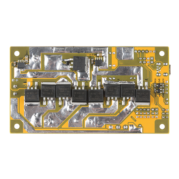
Did a simple check with the multimeter and saw that both the H-Brides outputs are connected together, so I checked your image from the back of the PCB and my PCB, mine has solder making connection between both FETs.
Could that be the problem?
Should I disconnect them?
If so what would be the best method?
Thanks.
Well that definitely looks like a mistake. The extra solder is placed on the tracks by hand to increase the current handling capacity of the tracks. If you have a soldering iron then you can just melt through the bit that should not be there. Otherwise, as the solder is soft you should be able to cut out the link with a sharp knife. Just be careful not to cut anything you shouldn't :D
The ACS712ELCTR-20A-T current sensors have an analog output however they need to be close to the "H" bridge which makes the analog output prone to electrical noise. If you are using a 7.4V LiPo then make sure you have the board in "low voltage mode".
Yep, forgot to comment, I've tested with the jumper on low voltage mode and without.
Be careful about changing voltage mode. Low voltage mode is only for 6V SLA, 7.2V NiMh and 7.4V(2S) LiPo batteries. If you use higher voltage batteries in low voltage mode then you can do permanent damage to the board.
I'm curious how heatsinking would work for this board. Would the heatsink be attached to the plastic case of the transistors (on the backside of the board)? If so, I didn't think much heat was dissipated through the plastic, I thought it was mostly through the transistor tab?
These are all SMD FETs, there is no big tab to screw down onto a heatsink so yes, additional heat dissipation is done by the plastic body. I think you will find the engineers who designed these electrical components thought of these things and used a dense plastic that has relatively good thermal conductivity.
Note that the board is only rated for 18A continuous per motor despite the fact that the "H" bridge FETs are rated at 85A each. The 4 layer PCB is designed to dissipate the heat evenly throughout the entire PCB thus becoming a heatsink.
For applications such as the Wild Thumper and T'REX tank chassis which this controller was designed for, no additional heatsinking will be required.
Dear Oddbot, My daughters and I have built about 35 robots so far (beatty-robotics.com), including two configurations of the Wild Thumper and the old Wild Thumper Controller. In general, I think your products are great, but we encountered an issue that you should be aware of on this new T'Rex controller. When we installed the T'Rex into the Wild Thumper Chassis using the supplied standoffs, and then powered it up on a 11.1v battery and turned it on, the board poured out clouds of furling smoke and stunk up the room. We immediately turned it off. We checked our polarity, etc., all OK, so then we removed the controller from the standoffs and tested it again. This time it came on OK. We then mounted it onto the standoffs and turned it on. Filled the room with smoke again. So we immediately turned it off. It turns out that when you mount the board on the standoffs the underside of the circuit board (which has long thick areas of solder) is resting on the chassis's top center socket head set screws. It's shorting out and causing a major draw in amps. Assuming we haven't missed something (please let us know if we have), then your company should probably rethink the design a little bit. Perhaps make the standoffs a bit longer or move the center chassis screws down on a notch. We've encountered stuff like this before, so it didn't take us long to figure out what was causing all the smoke, but if a beginner encountered this problem, it would probably cause some major frustration and damage to the board (we're not sure if our board is damaged until we get further into the construction). In the short term, for Sparkfun customers, I think the problem could probably be easily avoided with some insulating tape on the screw heads. In our case, we removed the chassis screws and moved them down a notch, but because the screws are internal to the assembly, this took an alan wrench, needle nose pliers, and about 20 minutes of wrist-crunching fidgeting around. Normally that's not too big of a deal, but in this case, we're building the prototype robot for a robotics workshop where 30 kids at a time will be building a complete autonomous and RC robot in a 3 hour period. So, every second counts. It's going to be hard to complete the build if all the participants have to take 10-20 minutes to move the two screws. One of the reasons we selected the Wild Thumper Chassis was because it was already mostly assembled and ready to go. We'll explore what we can do. Perhaps we'll employ the tape idea, or perhaps provide a different set of standoffs, or perhaps provide the participants with really good tools so that they can get down into where the screws are. Please let us know if we're missing something or if you have any other ideas for how we can make this a streamlined, easy-to-build process. —Robert
I checked to see what spacers are included with the T'REX as another customer had the same complaint.
Included with the T'REX controller are 4x 30mm and 4x 6mm brass hex spacers. When mounting in the Wild Thumper these spacers need to be joined together to make 4x 36mm spacers. This will hold the PCB high enough to prevent any short circuit.
Follow-up: I hooked the T'Rex up on a basic RC transmitter/receiver. It sort of worked for a little bit on the bench. The wheels turned in response to throttle movement, etc., but the slightest bit of movement caused little bits of smoke to come up. Then it got worse. Now when I give it throttle, the whole board resets itself. When I checked the back of the T'Rex board, the large black component labeled "110P04-05" looks like it has black marks around it and it's cracked. It clearly has suffered damage, probably overheating damage. I don't see any other visually obvious problems on the back of the board.
I think that my initial problems with the board touching the chassis screw might have toasted it. Not sure. I'm a little surprised it worked at all the way it did for a while. I've ordered a new one from Sparkfun Next Day Air so that I can continue my project ASAP. Other than my initial problem where the soldering on the back of the board shorted out on the chassis screws, is there something I might be doing wrong that could be causing this smoking/overheating/toasting problem? —Robert
I got my T'Rex controller from Robotshop and ended up with a self inflicted issue as well - same part got affected.
From what I've gathered, that part is a P Channel MOSFET. I'm not sure of the function (no schematic). I'm guessing it might be used as a way for the board to disconnect battery voltage, or maybe it's for the external power switch input somehow...I haven't fully reverse engineered the board....but I was able to bring my board back to life by bypassing this component with a wire, shorting the drain and source pins. I think what caused my issue was also the chassis screws. They're mounted just low enough that I didn't notice them touching the bottom of the board when inserting it in the battery compartment, but the supplied standoffs still allow you to mount it.
Replacement FET on the way - here's hoping it's the only damaged part. If anyone happens to have a schematic, that would be lovely. :)
Thanks for the update deveauzt. I've spoken with the designer of the board and sent him a description and pictures of what happened so that the manufacturer is aware of it. When he saw my pictures he said..."It's pretty obvious from the second photo that battery power was shorted. That Pch FET with the crater in it is the 110A high curret switching FET that allows a normal, cheap power switch to switch the high currents the controller can handle. Looking at the first photo I would say that it's a good chance the Switchmode regulator also got fried. In that case the 5V regulator might be trying to step 11.1V down to 5V when normally it would be reducing 6.2V to 5V. (Just a guess). That might explain the wisp of smoke since the input capacitors on the 5V regulator are only rated for 10V. That might explain the wisp of smoke since the input capacitors on the 5V regulator are only rated for 10V."
That may help you in your understanding of the board. In my case, I chucked the first one as a casualty of war, and got a new one. I put it on my own standoffs. It has worked perfectly ever since. I like the board. However, I do wish it had more available digital pins to add sensors to, etc. You can use the so-called servo pins as general I/O pins, but I still need more.
I have a similar issue. It looks like my 110P04-05 is fried. If I feed 13.5V to the input pins, it reads 1.8V on the other end. In my case, this happened after my bot got stuck and presumably pulled too many amps. I have a 20A fuse at the battery and also before the motors, so current should have been below 20A. I'm wondering why it blew.
I'll try bypassing it and see how that goes...
Does anyone have a good replacement part number for this component?
That makes me feel better/more comfortable about bypassing the FET - I have my own switch on my battery pack anyway - I don't use the external switch input at the moment - just left the jumper on the switch bypass as per default. From your description it sounds like your board may have fared worse than mine - though I'm using it in low voltage mode....I think the switching regulator is unused in that mode (could be wrong).
Is what it is I guess. The moral of the story for me was "watch out for metal chassis screws".
deveauzt
did you get your board running after the fix?
Just thought I'd add I had a similar case; just as a quick test I threw the TRex in R/C mode with wheels up on the bot, and all was fine. Gave it a run around the living room a bit, saw a small flash on the board (arc-like), and after that giving it any throttle would just reset the TRex and it wouldn't drive the motors. Pulling motor connections prevented the reset upon applying throttle. After reading other reports of issues on here, before much troubleshooting I just tried bypassing the main power cut FET since I already had a high-current toggle switch for power anyway, and I'm back in business. - by the way, while testing I had the board in a plastic box, so my FET toasting was unrelated to any chassis screws, and seemed like more of a defect in design or production.
Update: I'll preface this with I am probably pushing the limits of this board to begin with, mentioned in another post below, ~100lb 24v system: - I gave it a run outside for a few 15-30 or so second cruises, shut it down, and checked to see how temp of FET's was in case things were going to heat up quickly. They were barely warm to the touch, so the current handling seems to be great on this board. After a few cruises around the yard and everything was running smoothly, I thought I'd give the hill a run. I rolled down it, got to the bottom, and the board was toast. In my completely non-expert opinion, it seems to be the board maybe doesn't handle reverse / 'free wheeling' current in the H-Bridge well, as it barely warmed up under high load, and performed great, but with motors spinning rolling down a hill with no throttle (or very little), the board gave out. It now just has a dimly lit fault led on one side, and doesn't respond to RC input (or even do the three beeps at power up) . If OddBot or spartkfun has any input on if this board is resurrect-able, and/or if some external reverse protect diodes to supplement the body diodes of the FET's might get a replacement board by, let me know. I'd be happy to work with either to try to get this up and running.
I too have suffered a similar fate :-(
Got my T Rex, mounted it in the WT, connect battery...then a big bang and puff of smoke.
Did I get it right that I can just by-pass that FET, ie solder a wire between the two pins of it?
If it's the same FET affected, if you mounted it the same way and it had the exact same failure mode....then I can say yes - it worked for me.
That's a lot of "if's". Robert451's issue sounded a bit different than mine for example - he may taken out his switching power supply as part of his damage.
It's tricky to say anything for sure unless you start troubleshooting with a meter, etc. Would depend on your technical ability, otherwise you'd probably want to talk to tech support.
Will this still work easily with the E-Flite LP5DSM?
There is a standard that all RC systems should adhere to. Essentially each servo signal is a pulse between 1mS and 2mS wide that is repeated every 20mS. A pulse width of 1.5mS is servo center. In reality the range of the pulse width and the repeat time can vary between different manufacturers.
Unless your transmitter is made to a completely different standard then it should work fine. You can always tweak the T'REX sample code to suit your transmitter if required.
Hey OddBot,
I'm assuming that it won't be powerful enough to drive two of these without modification:
http://bit.ly/17g2e2E
I'd be using lead acid bike batteries and an aluminium frame.
I think a 24V 280W scooter motor is probably beyond what the T'Rex was designed to power. I'd think you'd be better off with a controller designed for scooter motors.
I can't open your link so I can't answer the question. I'm sure if you download the manual and read it carefully your question will be answered.
I just thought I'd double check I'm not mis-reading something, but it looks like in the user manual (page 13) this TRex is rated at only 9A constant per h-bridge/motor, and not 'average currents of 18A per motor' as stated in the description here?
The confusion lies in the PTC fuses. If you look on page 14 you will see that 9A is the current that the fuses can handle continuously (hold current). With a continuous current of 18A they will trip after about 20 minutes (depending on ambient temperature). The maximum current they are rated for is 40A.
The PTC fuses were chosen because they are self resetting and their slow response means they will not trip if your motor only stalls for a few seconds which can be annoying.
The FET's used in the H bridge are rated at 85A each assuming adequate heat sinking.
Thanks for the clarification! - So I've got a probably about 100+lb lawn mower based off of a power chair I'm looking to replace the controller on. Running at 24V and climbing some 45deg hills while mowing, I'm betting the motors are pulling well over the 9A each, possibly even over 9A on more 'normal' terrain still. It sounds as if this is well designed with the PTC's being the weak link, If I found I was tripping them after a decent period of mowing time, if I was heat sinking the FET's and maybe fan cooling, I'm thinking I'd be pretty safe replacing the PTC's with something of higher value (possibly even just a non-PTC)? - Thanks in advance for any input!
Yes you can replace the PTC Fuses. You can get a bi-metalic self resetting fuse for cars and trucks. They are bulkier so you would need to mount them off of the PCB.
For your application I think a heatsink and fan would definitely be a good idea. Although the 4 layer PCB does act as a heatsink this is really only suitable for the Wild Thumper and soon to be available T'REX tank chassis.
Is the brushless restriction only for the braking?
brushless motors work entirely different from brushed motors. A brushless motor connected to a brushed motor controller will not work at all and vice versa (well, some brushless ESC's do have a secondary brushed mode, but most don't).
You cannot use brushless motors with this controller.
anything for brushless motors? I want to replace the control board in my RC car. This would be great for speed/angle controlled steering!
Brushless motors need a 3-phase motor controller. The T'REX is only designed for DC brushed motors.
Dagu calls this the "T'REX robot controller", and people should not confuse it with the Pololu TReX motor controllers: https://www.sparkfun.com/products/retired/8900 http://www.pololu.com/category/96/pololu-trex-dual-motor-controllers
We were not aware of the Pololu TReX product when this product was named. Fortunately we named it slightly differently.
This looks like a great controller! How many standard I/O ports from the Arduino are left open?
Most I/O pins have been used for motor control, battery monitoring, current monitoring and the 3-axis accelerometer.
The only I/O pins left are the pins for the servos D5,D6,D7,D8,D12 & D13. The I2C pins A4 & A5. The serial interface pins D0 & D1.
It should be noted that the power pins next to D5 & D6 are 5V and Gnd which can be used for servos or sensors such as encoders or the RC inputs. The digital pins D7,D8,D12 & D13 have 6V and Gnd for powering servos.