- Home
- Product Categories
- Arduino
- SparkFun FTDI SmartBasic

SparkFun FTDI SmartBasic
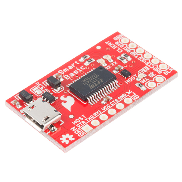
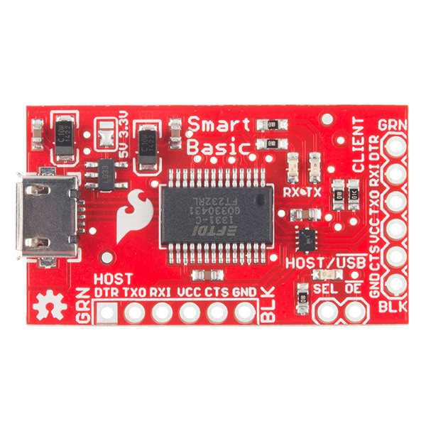
The SparkFun FTDI SmartBasic is a variation on our classic FTDI Basic board which allows you to connect a second device to the hardware serial port on an Arduino Pro, Pro Mini, or other USB-less board without compromising the ability to bootload code from the Arduino IDE. The FTDI SmartBasic hardware is pretty simple, it routes the serial signals from any board which uses the standard FTDI header footprint either to the programming PC via a USB-to-serial bridge or to any other device with a FTDI header.
Normally, to use a device which requires a serial port resource on an Arduino board, you would have to use a software serial port or plug and unplug the device during programming. The SmartBasic board adds a multiplexer to the serial port pins coming from the Arduino, which allows the application code to switch the serial signals from the USB port to another device. No special code is required to enable programming, either!
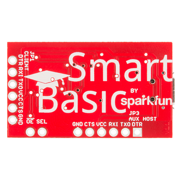
The SmartBasic uses the venerable FT232RL chip used on the original FTDI Basic boards and the TS3USB221A signal multiplexer from TI to make connecting to multiple serial devices easy. On this board you will find two main sets of headers, CLIENT (basically the same as the output header on a standard FTDI Basic board) and HOST (which can enable the application code to route serial data from the hardware port to either the USB serial bridge or the device connected to the HOST header). With this compact design and the power of TIs TS3USB221A multiplexer you should find no issues switching high-speed USB signals.
- Operating Voltage: 3.3V-5V
- TS3USB221A Multiplexer
- Switches High-Speed USB Signals
- Schematic
- Eagle Files
- Hookup Guide
- USB to Serial UART Boards
- How to Install FTDI Drivers
- Datasheet (TS3USB221A)
- GitHub (Example Code & Design Files)
- Product Video
SparkFun FTDI SmartBasic Product Help and Resources
FTDI SmartBasic Hookup Guide
October 3, 2014
How to use an FTDI SmartBasic Board to program an Arduino and access another serial device over the hardware serial port, without unplugging anything!
SparkFun USB to Serial UART Boards Hookup Guide
February 18, 2016
How to use the SparkFun FTDI based boards to program an Arduino and access another serial device over the hardware serial port, without unplugging anything!
Core Skill: Soldering
This skill defines how difficult the soldering is on a particular product. It might be a couple simple solder joints, or require special reflow tools.
Skill Level: Noob - Some basic soldering is required, but it is limited to a just a few pins, basic through-hole soldering, and couple (if any) polarized components. A basic soldering iron is all you should need.
See all skill levels
Core Skill: Programming
If a board needs code or communicates somehow, you're going to need to know how to program or interface with it. The programming skill is all about communication and code.
Skill Level: Rookie - You will need a better fundamental understand of what code is, and how it works. You will be using beginner-level software and development tools like Arduino. You will be dealing directly with code, but numerous examples and libraries are available. Sensors or shields will communicate with serial or TTL.
See all skill levels
Core Skill: Electrical Prototyping
If it requires power, you need to know how much, what all the pins do, and how to hook it up. You may need to reference datasheets, schematics, and know the ins and outs of electronics.
Skill Level: Rookie - You may be required to know a bit more about the component, such as orientation, or how to hook it up, in addition to power requirements. You will need to understand polarized components.
See all skill levels
Comments
Looking for answers to technical questions?
We welcome your comments and suggestions below. However, if you are looking for solutions to technical questions please see our Technical Assistance page.
Customer Reviews
3 out of 5
Based on 2 ratings:
9 of 9 found this helpful:
Switching between 3.3 and 5v is inconvenient to say the least.
Switching between 3.3 and 5v. Solder pads are just not acceptable and severely limit the utility of the board. The sort of person who has a need for the convenience of switching out the serial connection probably works with more than one kind of processor voltage as well. I was disappointed to not find a place for jumper pins or (better), a switch.
If increasing the size of the board is a price to pay, so be it.
I’m left trying to figure out how to implement that myself. The goal is not to tear up the contact points on the board. My best thought is to glue a micro switch onto the female connector and then run leads, using wire wrap wire, back to the solder pads. This will be delicate surgery.
A useful product, but...
The capability to simultaneously use these boards to program from USB and make a serial connection with another board looks useful, although I have tried it out yet.
My main complaint, as others have said, is the cumbersome requirement of soldering two pads together to change the operating voltage from 3.3V to 5V. I regularly switch between the two voltages, so having to unsolder and re-solder two tiny PCB pads was unacceptable. I spent a fair amount of time wiring in my own surface mount slide switch. Not easy or pretty, but better than the solder pad approach. I understand the concern about damaging a connected 3.3V board if this board is set to 5V. Having to re-solder tiny PCB pads is also risky. How about using a .1" jumper or shunt - not as easy as a switch, but a lot more convenient (and safer) than a solder bridge.
I'll make one more point that others have made. There is no way to mount this board, no mounting holds in the PCB. I have this complaint about many other Arduino PCB products. I understand they want to make them small, but I'd take the small increase in board size to be able to easily mount the boards.
It would be extremely useful to have the capabilities of this board built into the Arduino boards themselves. Imagine not having to disconnect I/O to flash new firmware...
I don't understand why this board costs 27$
Is this product a 'usb host' to rs232. It looks like it has a mircousb host socket. Am i correct?
It does not convert an RS-232 to be a USB host. Rather, it allows a USB port to perform the same functionality as an RS-232-type serial port.
If only this was pre-populated with female headers because I am not very good at soldering.
Good intention and I think it will work very nicely. But, why would someone need 900MHz bandwidth USB 2.0 data switch on this board that does 115200 as "maximal" speed? I'm considering a switch for my board but can't understand of the choice of TS3USB221A. Care to explain? Thanks.
I could make up something about bandwidth tests, possible applications, etc etc, but the simple fact of the matter is that I went to Digikey, considered the functionality and package size that I wanted, and picked the lowest cost option.
Ta-da!
OK thanks. The IC package is rather small. I'm looking for parts for my own board design. I can hand solder 44 pin tqfp. Never tried SSOP. Do you think I can do this by hand? You have breakout board I can grab?
It's pretty appallingly small- we had some issues during pre-production getting good reflow without a bridge under the chip. It's a leadless package, and worse, the pads don't come up the sides like on more traditional QFN packages.
I doubt we'll have a breakout for it, but you never know. It's not currently in development, I can tell you that.
If using a part that tiny isn't necessary, there are literally dozens of variations on analog switches to be had; the selection no doubt decreases if USB-level bandwidth is a requirement but you can probably still get somewhere.
The FTDI 232RL supports 3Mbps data rates, you might be using the pins on your target for something other than just serial. Using a higher bandwidth switch gives you options. Not everyone using these will be using them with Arduino boards. I have used the FTDI Basic Breakout with Propeller chips, a TinkerKit DMX Shield, rescued numerous bad flashes of routers, etc.
Hey, nice job with the FTDI SmartBasic :) The link however to the GitHub repo is not working!
Fixed. Sorry about that!
Why Do not put in your boards holes for mounting screws ?? In my opinion they are very comfortable for boards that can not be embedded in the breadboards ...
On a future revision, you should be able to add automatic switchover to the programming port without adding substantial cost to the board. Perhaps a small microcontroller that detects activity from the programming side (Reset), then switches the multiplexer and relays the reset pulse so that programming begins. Once activity from the programming side ends, it can switch back the multiplexer and again reset the Arduino so that everything fires up correctly with the external serial hardware. That would make everything a lot easier, and transparent to the main program on the Arduino.
Nice, but in the next revision, please put a smd switch to select the 3v3 or 5v operation voltage, no more solder!
I always hack the FTDI basic that way. I use the SMD switch. https://www.sparkfun.com/products/597
Good idea but the difficulty to swap between 3.3/5V was by design. I've fried a few boards when I didn't notice my bread board power supply was set to the wrong voltage so we're hesitant to add a slide switch to this board. A solder jumper is a good way to allow for flexibility but avoids accidental switching when the board is in your bag or when you're moving around parts on your project.
idk if that is a good idea. Switching the operating voltage while live may be a bit risky. I wouldn't trust a potential kill-switch that may damage the device and possible whatever its connected to. Rather own 2 separate ones with each configured properly instead.
I've used a jumper to select between 3.3 and 5 volts before while leaving it plugged in (to the computer, not a connected device). The power light will be off while the jumper is removed, but the USB link still stays functional, and it seems to be working fine! Even if SparkFun just put a footprint for a jumper or SMD switch, that would be better than nothing, though. If they did that, they should still keep the solder jumper for semi-permanently setting the voltage of the breakout.
I tend to cut the jumper, and power the I/O from my target.