- Home
- Product Categories
- Distance
- LIDAR Lite

LIDAR Lite
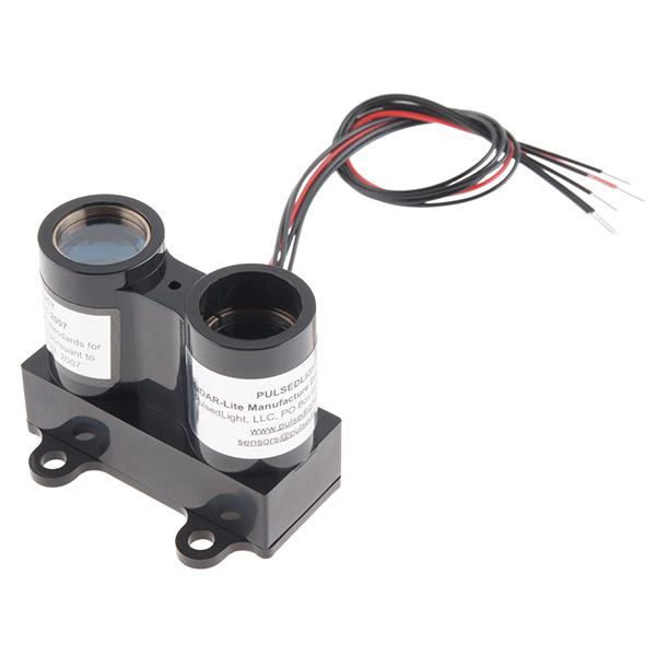
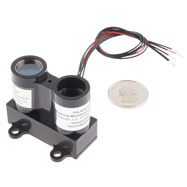
This is the LIDAR Lite, a compact high performance optical distance measurement sensor from PulsedLight. The LIDAR Lite is ideal when used in drone, robot, or unmanned vehicle situations where you need a reliable and powerful proximity sensor but don't possess a lot of space. All you need to communicate with this sensor is a standard I2C or PWM interface and the LIDAR Lite, with its range of up to 40 meters, will be yours to command!
Each LIDAR Lite features an edge emitting, 905nm (75um, 1 watt, 4 mrad, 14mm optic), single stripe laser transmitter and a surface mount PIN, 3° FOV with 14mm optics receiver. The LIDAR Lite operates between 4.7 - 5.5VDC with a max of 6V DC and has a current consumption rate of <100mA at continuous operation. On top of everything else, the LIDAR Lite has an acquisition time of only 0.02 seconds or less and can be interfaced via I2C or PWM.
Note: The LIDAR Lite is designated as Class 1 during all procedures of operation, however operating the sensor without its optics or housing or making modifications to the housing can result in direct exposure to laser radiation and the risk of permanent eye damage. Direct eye contact should be avoided and under no circumstances should you ever stare straight into the emitter.
- Range: 0-40m Laser Emitter
- Accuracy: +/- 0.025m
- Power: 4.7 - 5.5V DC Nominal, Maximum 6V DC
- Current Consumption: <100mA continuous operation
- Acquisition Time: < 0.02 sec
- Rep Rate: 1-100Hz
- Interface: I2C or PWM
- 21 x 48.3 x 35.5 mm
LIDAR Lite Product Help and Resources
Core Skill: Soldering
This skill defines how difficult the soldering is on a particular product. It might be a couple simple solder joints, or require special reflow tools.
Skill Level: Noob - Some basic soldering is required, but it is limited to a just a few pins, basic through-hole soldering, and couple (if any) polarized components. A basic soldering iron is all you should need.
See all skill levels
Core Skill: Programming
If a board needs code or communicates somehow, you're going to need to know how to program or interface with it. The programming skill is all about communication and code.
Skill Level: Competent - The toolchain for programming is a bit more complex and will examples may not be explicitly provided for you. You will be required to have a fundamental knowledge of programming and be required to provide your own code. You may need to modify existing libraries or code to work with your specific hardware. Sensor and hardware interfaces will be SPI or I2C.
See all skill levels
Core Skill: Electrical Prototyping
If it requires power, you need to know how much, what all the pins do, and how to hook it up. You may need to reference datasheets, schematics, and know the ins and outs of electronics.
Skill Level: Competent - You will be required to reference a datasheet or schematic to know how to use a component. Your knowledge of a datasheet will only require basic features like power requirements, pinouts, or communications type. Also, you may need a power supply that?s greater than 12V or more than 1A worth of current.
See all skill levels
Comments
Looking for answers to technical questions?
We welcome your comments and suggestions below. However, if you are looking for solutions to technical questions please see our Technical Assistance page.
Customer Reviews
4.1 out of 5
Based on 13 ratings:
5 of 5 found this helpful:
Perfect
I've been dabbling for over a year now trying to measure distance from 0 feet (with a 5 foot offset) to something over 30 feet. I have tried a variety of ultrasonic sensors and a fancy light ranging device from Canada.
This product is light, well documented and performs so beautifully that I now have expectations of ranging from 0 to 100 feet as I fly over the ground.
I would like separately colored wires rather than just red but that is on the wired connector which they supply and I can replace that myself if it annoys me too much and, too be completely unreasonable, I would like the option of purchasing an aerodynamic casing.
I am very happy with this purchase.
4 of 4 found this helpful:
Great device!
Students at the Colorado School of Mines are using the LIDAR Lite on a rover that will compete at the NASA Robotic Mining Competition in May 2015. It has a combination of distance and accuracy that you don't see with other distance measurement devices. It's easy to use and integrates nicely with standard hardware/software interfaces. We're really liking it. It quickly became the range finding device of choice over a couple other options we were evaluating.
1 of 1 found this helpful:
Great little gadget...
I played with this great little gadget,mounted it on a pan-tilt attached to an Arduino and managed to make a room scan showing depth map... Unit performs good but I have to note a small issue of measurement readings a little beyond stated limits... The problem may be servo noise from pan-tilt... The guys at Pulsed Light are cooperative and we are trying to find the cause... Details of my project at: http://myrobotlab.org/content/lidar-lite-distance-measurement-and-creating-point-cloud
6 of 6 found this helpful:
Impressive performance, but some caveats
I've played around with ultrasonic distance sensors but this device is quite significantly better; better response time and much better range, in my case up to 35 meters outdoors to trees, grass, sidewalk etc. You can't assume every ranging pulse will be accurate, but most of them are. If you want range to an object for under $100 this is the best solution I've found. I have not had the I2C lockup some reported (EDIT: at first...) but I do have extra capacitance on the +5V power (10 uF + 0.1 uF).
EDIT: It works OK if you allow 20 msec or more between reads. BUT, if you want to run this sensor at the maximum data rate, be prepared for what appear to be some hardware bugs in the device causing I2C SDA-low glitches, and/or lockup with the LIDAR-LITE holding SDA low permanently. See also: https://forum.pjrc.com/threads/28036-Translating-Lidar-Lite-I2C-example-to-Teensy?p=70237&viewfull=1#post70237
EDIT2: if you are using this at longer ranges, eg. outdoors (> 5 meters) be aware that the output is not just one laser beam direct out the lens. On my device at least, there are two much fainter, less-focused secondary beams going out about 30 degrees from the main axis, from some internal reflection I suppose. This has no effect EXCEPT if you put the device in an enclosure where these beams can bounce around inside, you will get spurious readings from 10-40 cm when the true range is around 25 meters. You can fix this by adding a black tube around the output beam and/or detector to conduct the optical path outside the enclosure and block the high-angle secondary beams from reaching the detector. Example photo: https://picasaweb.google.com/lh/photo/diAx1HgTlYxuR_hh1AMNIdMTjNZETYmyPJy0liipFm0?feat=directlink
I also made a 3D-printable shield tube: http://www.thingiverse.com/thing:769066
1 of 1 found this helpful:
It works really well. Frequency around 50 hz and 1cm of precision of distance mesure. Just a little instability when i make a static mesure. I presume that is a problème on my arduino mini and not on the sensor. Thanks to Sparkfun seven days to obtain the sensor that's really a nice service.
2 of 2 found this helpful:
Excellent Product
The product is very accurate, I have it cooked up to a Leonardo shield and wifi shield with SD card. No problem powering the whole works and coding it was simple if you can do basic searches.
As for comments made by another on shipping. I live in Canada I ordered from Spark fun, paid for it. Got my email about the order, I then I got a "shipped" and tracking was provided the entire time, I could watch the status. I paid for Fedex overnight - though I asked it only be delivered Monday to Friday at the office, it arrived through customs so quick it was on my desk Monday morning . Any shipping issues like are a result of the order placer than spark fun in many years I have never had an issue with them - issues with Canadian suppliers in Toronto -yes .
The staff at sparkfun also answered any question I had within in hours and I am very happy with them,
Comments to the Lidar the cables could use a bit better gauge my wire strippers did not go that low but I managed all the same.
Anyone having an issue with this product is not being self reliant and is expecting too much of others. You place an order and you pick cheap shipping you get what you get and that's your issue not spark funs.
3 of 3 found this helpful:
Works well, if you use delays
This module seems to have pretty good performance, if you avoid trying to communicate over I2C while it's busy making a measurement. Plan on waiting 20 ms, and don't try to use the I2C bus during that time!
If you try using the ACK/NAK feature to detect the moment it's finished, there are a lot of I2C communication bugs. It will pulse the SDA line low for several microseconds for no apparent reason, disrupting communication. If another query is done too quickly after a NAK, it will get stuck with the SDA line low, where the only way to recover seems to be cycling the power. A delay after reading the data, before starting another measurement is also needed, otherwise it will give a copy of the previous reading, or zero.
If you use simple delays and avoid I2C communication during those delay time, it's easy to use and works really well.
1 of 2 found this helpful:
Maybe is not totally true, but till now it is great fun tinkering apps.... Till now I am not convinced that its range is 40 meters.
regards
Jan
May just be a bad batch I got but seem buggy with I2C
Been trying to get working with APM and Pixhawk as rangefinder for above ground altitude and would tend to just lock up..
A PWM workaround has been developed and wonder if a firmware update will soon be available.
Hi, Sorry for the troubles. I may recommend contacting us at techsupport @ sparkfun.com we may be able to assist you. If we can't, we can point you in the right direction for more assistance from the manufacture. Thanks
Worth the money
The LIDAR Lite blew all of my previous ultrasonic rangefinders out of the water. With a range of 40 meters, my 2 meter ultrasonic sensors seemed wimpy. I used my LIDAR Lite in a autonomous, room mapping robot. This was one of my best buys from Sparkfun!
Seems to be very useful
Just got it up and running using C# with a Netduino plus2 breadboarded to the Lidar. Some occasional problems with I2C not working at startup but retrying seems to work. Getting good readings from cm to c.14m indoors through a doorway. Next step is to wire it up properly and build some mechanicals to adapt it to my robot's servo platform so I can build a room map. Only a couple of gripes. One is the cable that comes with it that consists of one red wire and the remainder coloured various shades of black. Second issue is the zero point for the measurements on the sensor. It's not the front of the unit... or the back. It does at least seem to be a constant offset somewhere inside the device so it can be factored in to close-up measurements. Overall though, a nice device at a reasonable cost.
Very impressive
This pruduct is amazing it is very accurate and easy to use plus the tecnology behind of this lidar is sick. However keep in mind that the cable is very hard to find and if it breaks like mine you might have to wait like a week to get a new one
Seem sensible enough, stable output and fast sample rate.
First Lidar trials on the table, interfaced with Bus-Pirate, was quite disappointing : spending a lot of time to get the two range bytes in only one I2C call. Recently, I found the solution : call with the MSB of first data address set to 1 (0x8F). To reach the maximum rating that I wish, I have to connect the Lidar with the UDB5, using the PWM interface. I hope reaching 40 Hz sample rate. Lets see soon in real world environment!
This thing works rather well. I'm getting good reading from 1/2' out to 40' with no issues. I haven't tested much past 40' ... I need a bigger room. This is a video of two of them working to scan 360 degrees of a room.
YouTube video
Did you 3d print that stepper motor jig that you're using? Ive been looking for something like that to do some desktop testing with steppers but I cant seem to find a good solution.
That's an awesome project!
Thanks ... It's very early in the development. I hope to get a dead reckoning chassis setup this weekend to allow the scanner to drive around. Then pump all the data into a SLAM algorithm.
You need to join the support forum group on our site. There's a group that are working on a similar project that would really like your input! Never Mind! I see you've already joined in!
;') ... I've been talking with the RoboBill a little on this. It's a young group but is full of great people. I backed your Dragon Innovation project and got some units early than many.
Well I owe you a double thanks!
I am super excited about this product, I see it is going to be great to do line scans (perhaps +- 20 deg) in direction of travel of my auto piloted RC car, also as the range finder under my plane or quad copter to get an accurate height relative to ground. Seems most time of flight range finders have this sort of accuracy, if you think about what is being timed it is pretty call how accurate it is, talking about timing with a resolution 0.1 nanoseconds.
Here is a good tutorial-based primer on the algorithms/math behind mapping and location-finding using LIDAR: SLAM for Dummies. The authors do a really nice job of wading through the jargon and presenting the SLAM in an approachable manner. It does have code examples, but they are written in C#. However, the examples are pretty straight forward, and shouldn't be too difficult to port into your language of choice.
What is the maximum velocity (relative to the target) at which the distance readings are still reliable? Because of the phase-based principle I assume there's a maximum velocity above ambiquities between distance and velociy can oocur. Is this correct?
I assume you're wanting to measure the velocity by comparing successive distance readings. Because it uses time-of-flight measurement, the distance readings shouldn't be affected by instantaneous velocity. However, the ability to obtain said distance readings could be impaired by the light pulse being Doppler-shifted too much for it to receive. At what instantaneous velocity that would occur would depend on the wavelength range in which it can receive, which I don't know.
Any thoughts on how well this would work pointing at a water surface?
It depends on a couple of factors. The 905nm source that's used in the sensor will penetrate into the water if it is clear and still. In shallow water, under 1m, it may actually read to the bottom. If the water is murky and turbulent you will have a better chance of reading the surface from directly above. You can also measure the surface from an angle, up to about 45 degrees, and get readings.
How useful would this be through angled glass, in terms of distortion? ie. sitting on a car dash looking through the windshield
Through plain glass it should be okay as long as it's perpendicular to the glass. For angled glass you would want to have a gasket between the individual sensor tx/rx optics and the glass since LIDAR-Lite transmits and receives at the same time and any reflections up close would cause crosstalk. Also low-e glass or glass that's been treated to be energy efficient will attenuate the IR significantly.
Typical glass attenuates IR significantly. Not sure about windshield glass though I can't imagine how it would not be even worse. There is a good chance it will not operate as well, if at all. In addition, ranging is based on time of flight which assumes the same medium for propagation. Light is slower in glass by a factor of 1/refractive index (which is a function of wavelength) so accuracy will be reduced due to air/glass/air/glass/air round trip not being the same as air round trip. Typical crown glass has nominal refractive index of about 1.52 so the glass thickness of say, 1/8 inch will look like roughly 1.52*1/8 =~ 3/16". Looking through slanted glass is worse because the actual glass path is longer, etc. I think I digressed a little.
I've wondered the exact same thing. I'm going to do some testing with it this weekend to determine exactly this. I'll post what I find.
What did you find?
PulsedLight kindly donated one to my First Lego League team and they made a working prototype using it. It is amazingly easy to use hooked up to an Arduino and it works great!!! I can't recommend it highly enough! (The team is composed of 9-14 year olds and they blew away the judges with a prototype where they had this hooked to an Arduino micro, an LCD, a push button, all inside of plastics they designed with TinkerCad and had 3D printed.) They won 1st place in Project Innovation in the North Carolina State tournament.
I am a little bit confused by the "range" characteristic on this product page : "Range: 0-40m Laser Emitter", while the range specified in the manufacturer datasheet it is 40m for the Led/Pin model and 60m for the Laser/Pin model ... Anyway, thanks for this nice new product :)
Sorry about the confusion! Our data sheet and operating manual contain info on several possible permutations of LIDAR-Lite. The product being offered now is the laser/PIN model with a maximum range in the 40-60m range. The maximum range, of course, will vary with the reflectivity of the target. We do plan on having shorter range LED based sensors available in the not to distant future.
Actually, the datasheet that I looked at specified a range of 20m for the LED/Pin model with optics. The Laser/Pin model is (as you said) 60m. The data sheet doesn't have a configuration for a range limited at 40m...
One thing that I'm not sure about (either the datasheet, Operating Manual, and Tech Brief don't mention or I didn't notice when reading all three) is where is the 0 reference for the measurement? The PIN diode or the front of the optics?
the zero reference is the top of the PCB which you can see on the connector side of the unit. You can, however, adjust the zero reference to be what you want by writing an 8 bit signed value in control register 19 (0x13). This currently is in volatile memory and would have to be reloaded at every power up of the sensor.
That's what I suspected. I missed the zero reference adjustment, but I only scanned the documentation. Good to know that one can program a zero reference in the sensor instead of having to calculate it in the application for every reading. (Loading a known constant at each power up is a trivial function for boot up).
The main reason for the zero reference question would be to figure out the best place for a center of rotation for a circular scanner. (Or even a scan-line type scanner to "map" a surface.)
Just getting this hooked up to work. Only comment so far is about the wiring harness. One red wire and five black ones...really?
Does anyone know if this would be suitable to replace a beam-breaking sensor?
If I understand correctly, the datasheet says "3 degree field of vision." So I am hoping I can treat the beam like a 3 degree cone.
The sensor I'm replacing is a line breaking sensor at the top and bottom of essential a row of cabinet drawers. I'm sensing if the cabinet drawers are accidentally left a little open. Sonic sensors, anything without the second sensor on the bottom, these seem to not have a tight enough beam for my application.
I know this is a somewhat pricey sensor, but perhaps it would work, unless I'm misunderstanding something. Not familiar with these, so if anyone could chime in I'd be very grateful.
Is it possible to extend the range of this by pointing it through a scope/monocular? Obviously if you double the range out to 80m the accuracy would go down as well, but I'm only looking for +/- 2 metres or better.
That would probably require modification of at least the firmware on it. A signal that travels twice as far will take two times as long to return (which is how it works), but the stock firmware will probably have stopped listening for a return by then.
I am assuming you should not look at a helicopter seeing as how it uses lasers...
Or does it use special lasers? Like infrared? EDIT: Confirmed, non-visible laser. It does use infrared!
Also, if you're within 40 m of a helicopter, you can probably aim a visible laser at some part of it that's not where the pilot's eyes are. But still, I wouldn't recommend doing that.
How laser supposed to work over different surfaces such as snow? grass? asfalt?
Will this device provide correct results if I put glass between it and an obstacle? I just want to protect it against rain or snow.
When I saw this I started thinking about using something like it to build a desktop 3D scanner. This model has a somewhat wide beam spread and is tuned to longer distances, but the same company seems to make a related model which is for shorter distances. My idea was for the scanned object to be on a turntable and the LIDAR unit to be on a acme screw on the Z axis - seems pretty straightforward. Is there any chance of SparkFun carrying the other models in this line anytime soon?
So wish there was an 80-100m version, want to meter a distance meter for my car for safe distance. Trouble is at 70mph a 2sec distance is about 62m.
Radar modules designed for that purpose can be bought cheaply from China. I'm pretty sure I saw them on AliExpress.
What is the spot size for this unit?? The size of a nickel or the size of a basketball?
What is the detection region like? Wide or narrow? Usually with distance sensors there is a picture depicting the region of detection.
Hi: We got one of these lidar-lite units this week and have been playing with it for an application in a FIRST robot.
PROS:
1) It is a dandy little gizmo, and seems quite accurate for at least 0.5 m to at least 20 m (all we have really tested or needed).
2) Responds quickly!
3) Light (as in grams). Could be forward-facing or mounted on a little stepper to sweep an arc.
4) Looks well-built. 5) Darned good price point for the specs. (compare at $1000-5000).
CONS:
A) Can be locked-up on close ranging (eg: moving your hand towards it), BUT they have a firmware update as of mid-Jan 2015 to fix it and you can also reset it via software if the lockup happens (cycle pin-2 enable) -- I am not complaining as this is indeed breaking-ground-price-point for this lidar technology, and being a new project, well, stuff happens. They have fixed it for new units, old units can be sent back for a firmware update, and you can detect the issue and reset if necessary, so fwiw. Still cool stuff. B) The pinout could be better. The supplied cable has a red wire for pin 1 (VDD) and black wires for the rest, but not interleaved ground and power to keep electromagnetic crap down (which has been a consideration for everything I have done for about 30 years now). I2C can be a nasty EMI radiation/susceptibility case, so for the lidar-lite I recommend that you twist pin 4 (SCL) with pin 6 (GND), twist pin 1 (VDD) with pin 5 (SDA), and just for symmetry you could twist the non-critical pins 2 (EN) and 3 (MODE) together. Since five of those wires are black, you need to mark them before you twist or you have no idea what is what. It is a really good idea to contain the emi antenna loops from SCL and SDA, and it is generally done using alternating GND/VDD lines in a ribbon cable. Well, except seeed, who also has it goofed up. Anyway, this lidar-lite cable lets you twist wires separately, so just go do that and be happy. Not a big deal, but something that an old gray-haired fart like me would do in a design to minimize potential problems.
<rant> INTEGRATING INTO 2015 FIRST ROBORIO: This is a specific use-case issue, as we have been unable to talk to simple I2C devices using the on-board roborio I2C port. Others have said that the onboard I2C port is problematic, though the MXP expansion I2C port is fine, however, FIRST rules require an approved "active" expansion board on the MXP port, so that is also a hassle. We may add a RIOduindo board to circumvent the overly-paranoid first mxp rules, but we still need to talk to that board from roborio. Since we are using C++ (and not java, or the goofy visual-programming vi stuff), we have no example roborio code on which to base an I2C design, despite having very good familiarity with low-level i2c-start/write/read/stop functionality, which seems to be abstracted to a level even more obscure than that done in the arduino wire lib. It is all very frustrating -- if anyone feels the pain through which we are going, and has a helpful hint or two to poke us in the right direction, we would be most in your debt. Sheesh, all we really need is some example code to talk from the roborio c++ to an i2c slave by writing and reading various bytes of our choosing, and we can easily do the rest of the slave code. The WPILib interface seems so very bizarre and is closed-source afaik, so we cannot just grab an i2c interface to a simple accelerometer or something and tweak it. Quite a bummer and very few weeks left in the competition. </rant>
Anyway, pardon the rant -- it is a great unit, but we are just having trouble integrating it into a specific platform. It is well-documented for general applications. If anyone is in the same FIRST quandry, well, let's talk.
SUMMARY: This is a very-cool little gizmo, even with a few first-gen issues -- love it!
thx, gil
So I purchased one the other week and tried it outside just to see what kind of practical performance I could get. It seemed like 25-30 m was about the best I could get. It was sunny, and the environment was a mixture of trees, fences, and buildings. It didn't seem like the sunlight hitting the sensor affected performance (shielding the receiver didn't change performance much).
So, at 1W is this eye safe for a spinning rangefinder?
It's a Class 1 laser and so safe under all conditions of normal use. You can safely look directly into the laser without worry of any eye damage.
This is a pretty neat product. Does anyone know how divergent the laser emission is? So, at 40-60m say, what is the approximate diameter of the beam?
The beam is a 1/2 degree, so, without doing a lot of math, at 10m it's about the size of a softball, 20m would be about a basketball in size and at 40m it's about .5m square.
Is the laser a visible dot?
No ... its in the infrared spectrum. It's hard to see with a camera.
Too bad - it doesn't sound like there is any way to know what it's looking at. You couldn't fit a laser pointer to one side due to parallax.
Actually, parallax is a tiny a problem, just mount the laser pointer immediately adjacent to the emitter on the Lidar and aligned with it and your offset will only be equivalent to the offset at the Lidar module itself, (a fraction of an inch.)
A much bigger problem is the possibility of the laser pointer laser compromising the return from the IR Laser at the Lidars receiver end. If the sensor is sensitive at all to the wavelength of the Laser pointer it can compromise, degrade or completely swamp the signal from the Lidars emitter diode.
This effect will depend on how narrow and effective the bandpass filter on the Lidars sensor is.
Great answer! One correction, however. The signal processing we use, would not be affected by the laser pointer beam at all. In fact, you could point multiple LIDAR-Lites at the same target and they would not interfere with each other!
You could adhere a laser point hooked to a servo and adjust for parallax based on the range it scanned. But no, there isn't a good way of mounting a visible laser pointer.
it seems cool but I'm having a hard time getting excited about a $90 range finder that is only accurate to +/- .025m (about an inch)...
I work with industrial grade lidars and I say $90 is pretty reasonable for these specs. Scanners I get to use are $5-50K each. If you want a faster refresh rate but shorter range, look into taking apart a robotic vacuum cleaner. There are many of them in second hand stores. When the battery dies people don't bother replacing it. You can have find a good lidar with a turntable or a prism built in for $10, and SPI data output.
50Hz rate is painfully slow though. I had an infrared scanner with such refresh rate, doing pixel by pixel mapping of a rectangular area. For a 800x600 output image it would take 2.7 hours in an ideal world, but if you add few milliseconds to command steppers, a little sync mismatch between the sensor and the microcontroller, you end up with actual run of about 4 hours. And you better hope your scene remains perfectly still all that time, and your battery packs don't run out. All for a less than half-HD depth image.
I agree. I cannot quite imagine what would be the application that can cope with a fairly low precision and only a moderate range. Not to mention the ~150USD price tag (with S&H, taxes, customs fees etc.). If, and this is a big if, this thing works underwater, I guess it could be useful for fishermen to (automatically) scan and map the lake bed, rocks, and what not.
Anyway, for an active/adaptive cruise control and/or collision prevention/warning system, 40 meters is not enough, nor is 60m. However, I reckon a similarly priced or somewhat pricier LIDAR with, say, 1-5m accuracy and max range in the 300-1000+m region would sell like cupcakes.
The update rate (50Hz), ability to work in full sunlight, long range, and tolerance to various reflective surfaces makes this perfect for mobile robotics. Nothing like it has existed for this price before. We've been looking a long time for this capability, and are very excited about this sensor!
What is the accuracy for under 3 feet. I'm looking for a sensor that can measure at less then a mm, but I don't need the distance. (sonic sensors just aren't accurate enough).
The resolution of the sensor is 1cm and at short range the accuracy would be around 1% of measured distance based on our testing. So LIDAR-Lite may not be what you are looking for in terms of absolute accuracy. A phase based rangefinder, like those that are sold for construction, might be you're best choice.
Assuming your post contains a typo ("Measure at less than a mm") and you meant measuring at less than a meter, the datasheet indicates an accuracty of plus or minus 25 mm at a max of 3 meters
The FIRST group I mentor just got two of them in and had them up and running pretty quick on the i2c.
Only note I have is at ranges < 30 cm the measurements seem a bit erratic.
But other than that very nice little ranger finder for any distance further out at a great price.
Correction, my group got the 60m ones but I am assuming the 40m are about the same.
Where did you find the 60m version? I could use one in a project that I've already started.
This thing looks awesome! It looks like there is a plug for a cable, will SFE sell replacements cables?
Here's the video Youtube video
Can't wait to get mine!