- Home
- Product Categories
- Distance
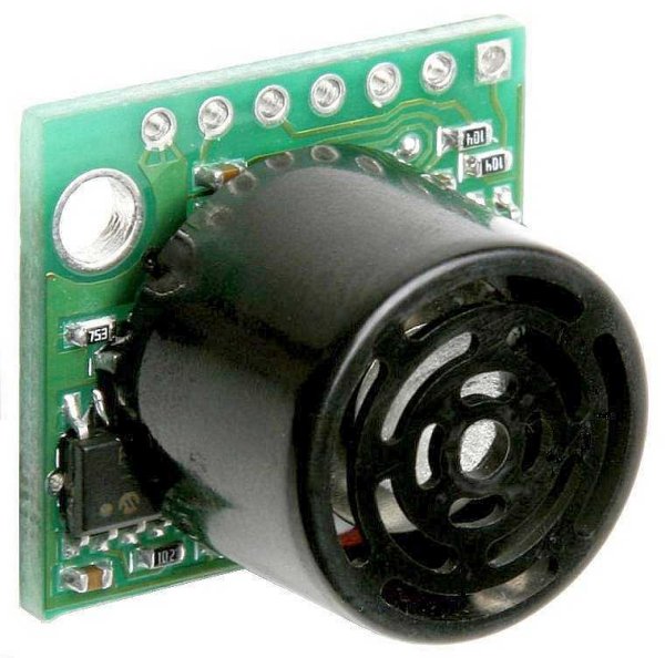
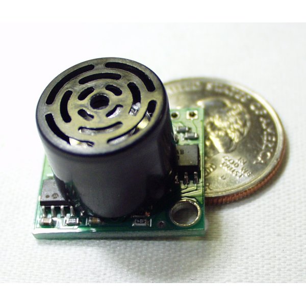
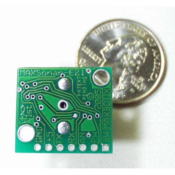
- Ultrasonic Range Finder - LV-MaxSonar-EZ4

Ultrasonic Range Finder - LV-MaxSonar-EZ4
This is the fantastically easy to use sensor from Maxbotix. We are extremely pleased with the size, quality, and ease of use of this little range finder. The serial interface is a bit odd (it's RS232 instead of TTL), but the PWM and Analog interfaces will allow any micro to listen easily enough. The sensor provides very accurate readings of 0 to 255 inches (0 to 6.45m) in 1 inch increments with little or no dead zone!
Maxbotix is offering the EZ0, EZ1, EZ2, EZ3, and EZ4 with progressively narrower beam angles allowing the sensor to match the application. Please see beam width explanation below.
Control up to 10 sensors with only two pins! Checkout the Maxbotix FAQ listed below.
- 42kHz Ultrasonic sensor
- Operates from 2.5-5.5V
- Low 2mA supply current
- 20Hz reading rate
- RS232 Serial Output - 9600bps
- Analog Output - 10mV/inch
- PWM Output - 147uS/inch
- Small, light weight module
- Datasheet
- Beam Width Explanation
- Maxbotix FAQ
-
Checkout Mikey Sklar's flame-based trampoline, the high-lighter, using the EZ1!
Ultrasonic Range Finder - LV-MaxSonar-EZ4 Product Help and Resources
"RS232" Output or Inverted TTL
If the ultrasonic range finder indicates that it has an "RS232 Serial Output" and is outputting an inverting signal with the voltage level based on Vcc, you could just use an inverting circuit using a transistor to invert the signal. This is not a standard RS232 that uses +/-12V. There are a few methods of flipping this signal through hardware or software. The resources and going further will provide specific examples.
Inverting Signal w/ Hardware
Doing a quick test using a retired NPN transistor from our storefront, I was able to get it working based on the circuit using a RedBoard Programmed with Arduino. I was using an Arduino so Vcc in my circuit was 5V. Since it's basically two diodes within the transistor, you will want to use resistors to limit the current. I just used two 330Ohm resistors just like I was turning on an LED. You probably do not need to do this but the values might need to be adjusted when using it at higher speeds or if the transistor is not fully turning ON/OFF. Testing with a multimeter, it worked as expected. An input of 5V would result in 0V (logic LOW) on the output since the transistor was turning on. With an input of 0V, the transistor would not be conducting so the output would be held HIGH at 5V. Using an Arduino serial passthrough for further testing, I was able to view the ultrasonic sensor's output data without any problems.
"RS232" Output and Inverting w/ Software
Otherwise, you could be clever in writing your code to store the value and possibly apply some sort of logical NOT operation. In Arduino, there is a special feature using software serial that inverts the signal by setting a parameter to true [ "Software Serial Constructor" – https://www.arduino.cc/en/Reference/SoftwareSerialConstructor ]. There was someone in the Arduino forums that provided example code to invert the output, parse the data, and output it through the serial monitor here => [ User "Goldthing" - http://forum.arduino.cc/index.php?topic=114808.msg864009#msg864009 ].
Connecting Ultrasonic Sensor to Raspberry Pi
There is a tutorial from MaxBotix that shows you how to connect ultrasonic sensors to Raspberry Pis => [ http://www.maxbotix.com/Raspberry-Pi-with-Ultrasonic-Sensors-144/ ]. Certain ultrasonic sensors listed in the article require an inverter. If the ultrasonic range finder's output serial output is " RS232 " like the sensors listed under "Ultrasonic Sensors that Require an Inverter" , this indicates that the signal is basically an inverted output with the voltage level based on Vcc.
Therefore, you would need to follow the tutorial and use a serial inverter in order to use it with the Raspberry Pi. If you are using a Raspberry Pi a transistor, Vcc should be 3.3V since the Pi uses a 3.3V system.
Resources and Going Further
Core Skill: Soldering
This skill defines how difficult the soldering is on a particular product. It might be a couple simple solder joints, or require special reflow tools.
Skill Level: Noob - Some basic soldering is required, but it is limited to a just a few pins, basic through-hole soldering, and couple (if any) polarized components. A basic soldering iron is all you should need.
See all skill levels
Core Skill: Programming
If a board needs code or communicates somehow, you're going to need to know how to program or interface with it. The programming skill is all about communication and code.
Skill Level: Rookie - You will need a better fundamental understand of what code is, and how it works. You will be using beginner-level software and development tools like Arduino. You will be dealing directly with code, but numerous examples and libraries are available. Sensors or shields will communicate with serial or TTL.
See all skill levels
Core Skill: Electrical Prototyping
If it requires power, you need to know how much, what all the pins do, and how to hook it up. You may need to reference datasheets, schematics, and know the ins and outs of electronics.
Skill Level: Competent - You will be required to reference a datasheet or schematic to know how to use a component. Your knowledge of a datasheet will only require basic features like power requirements, pinouts, or communications type. Also, you may need a power supply that?s greater than 12V or more than 1A worth of current.
See all skill levels
Comments
Looking for answers to technical questions?
We welcome your comments and suggestions below. However, if you are looking for solutions to technical questions please see our Technical Assistance page.
Customer Reviews
1 out of 5
Based on 1 ratings:
WHAT. ON. EARTH.
Summary: Never been accurate at all with me. Not exaggerating. Managed to use it for precision measurements for a project of mine by correcting the deviation of readings in my program. But absolutely useless for anything else. Probably have faulty units.
Full: I got 2 of these sensors, and first time using either one (using the PW pin, not the Analog, and inputting in 5V), got 56 inches as the initial value (whatever the reading divided by 147), even though my hand was right above it (2 inches max). To make things worse, putting my hand a way so that it would read the ceiling above (at 75 inches) changed none of the readings. It stayed at 56. Then tried absolutely everything. Used both the analog and PW pins through multiple runs (each one giving completely different values btw - first time 56, then we went to 60, then 42, then 78, and so on), neither ever gave anything anywhere near accurate - I mean unbelievable. Tried 2 different capacitors (100 and 110 microfarad) and no capacitor at all. Gone through forums. So much just to get a SOMEWHAT accurate reading from these things, but to no avail whatsoever. The only thing this was good for was challenging me programming-wise to manage to gain some precision from these things by using averages, finding the mode, and constain() function (which basically made the values used binary - 0 if there was something within an inch of it, and 1 otherwise), which worked for the project I was working with it on. I might have had faulty units (which is incredibly frustrating considering I live very far away and this takes forever to reach here) or somehow it got damaged before I used it. Either way, very unhappy.
looks like a very interesting product range...but they've got to get rid of the christian cross and jesus fish traces on the bottom side of the board. this is gratuitous and doesn't belong on a product such as this.
i'll take my electronics secular, thank you very much.
I think that the manufacturer of this product should have the freedom to put whatever they want on the product they make, it's totally the consumer's choice to purchase the item.
The "1st" mention is an insult to anyone believing Mohammed is 1st. You can print "I love Jesus" cause yuo can love whoever you want and share it. You cannot tell people that their prophet is not as good as yours. It really is disrespectful.
The EZ4 has a range of only about 14"max, 6"min.
btw, They have the right to put the cross and fish on the board just as much as you have to complain about it, and just as much right as I have to agree with or without it.
No one is forcing you to buy it. Move to China or NK if you don't like our freedoms.
I too was annoyed that the manufacturer sees my buying of a proximeter as a moment to secretly (there is no way to notice before purchase that this is not a proximeter but a Christian proximeter unless you know to check for it) advertise their religion to me.
As you say, this is their right just as it is my right to never purchase this item again and to ask Sparkfun to either remove the item or let their customers know that this product comes from a proselytizing company and by purchasing this product you are supporting the advertisement of religion.
I was able to avoid hitting Jesus while driving the other day - great product!
Any chance of a non-religious version coming out? My PCB doesn't have enough space for fairy tales.
How is the accuracy compared to the $2 HC-SR04 modules?
I created a housing for this in openScad that you can 3d print -- It is available on Thingiverse.
http://www.thingiverse.com/thing:38531
Update, The problems commented about are do to a faulty sensor. It is being replaced at NC.
My problem is that I need a sensor which is used to find the river bed depth. I tried using ultrasonic sensor placed in air, the signal reflects at air-water interface, working just like level detector. So I decided of placing the sensor in water to serve the purpose. Can I place the sonar or ultrasonic sensor in water with waterproofing? Will it give a solution to my problem? Please help me to arrive a solution. Thank you.
can this sensor applicable on PLC??????
So what is a simple cable configuration to connect this with a board? I thought that the PRT-09915 - JST Jumper 3 Wire Assembly might do the trick, but the pins are a bit too close together.
i'm desperately seeking a way to color the plastic front of the range finder white. i tried carefully painting it but think it broke the sensor (unsurprising). does anyone know of a clever way to get this done?? thanks!
its giving a range of 6" to 14" max, after which it gives 251".Whats the problem?
I'm considering using one of these sensors to build my own open source liquid level sensor. The idea is to mount one of these at the top of a 2 or 3 inch diameter PVC pipe mounted vertically in my aquaponics sump and then put a slightly smaller round piece of wood (float) within the PVC pipe to rise and fall with the water level.
Does anyone have any advice on...
a) whether this idea will work and b) what sensor I should select for this project?
I have looked at prefabbed liquid level sensors on this site and others, but they are twice the cost and only measure a maximum of 2 feet. I only need to measure to a depth of three feet, but my project is open source and others may have greater distance needs for their aquaponics systems. If you'd like to learn more about my aquaponics project you can check it out at opensourceaquaponics.com
Thank you for your consideration! ~ Will
So the serial on this thing is +-13V that it generates from 5V somehow? Would http://www.sparkfun.com/products/133 work to get a uC to read the sensor?
Can anyone tell me if this will this work through my car's window? Thanks.
No, it won't, you'll need a laser range finder for that.
Will this work through my car's radiator grill?
If there is a clear path (no objects) between the sensor and the object you are trying to detect, the sensor will work fine.
This thing is awesome. Connecting to an arduino through the analog was very easy. I put one on the front of my robot to do obstacle avoidance, and have recently been experimenting with making 3d sonar maps. I am documenting my experiments at http://www.glowseed.com/mindmash
Also, the Analog output doesn't function properly. With a 5v input, the AN messures 1.67v in the open, and 1.54 when bloked within 4 inches of the sensor, No ranging.
There also seems to be no 0" range detection as it claims.
Perhaps I have a bad one.