Enginursday: RS-232 vs. TTL vs. Inverted TTL
Today, we revisit the concept of serial communication with RS-232 and TTL. We'll also explore the "inverted TTL" with the ultrasonic range finder to read data from the sensor.

Today, we revisit the concept of serial communication with RS-232 and TTL. We'll also explore the "inverted TTL" with the ultrasonic range finder to read data from the sensor.
How to Connect the MaxSonar's Ultrasonic Pins to UART Pins?
While I was in tech support, there was a customer who asked how to connect to the ultrasonic range finder's UART pins and read the output. I knew the sensor could be powered at around 5V from a previous tutorial that used its analog pin. Therefore, I assumed that the input was TTL with a voltage range of about 0V to 5V. Depending on the circuit, the signal has a voltage range of 0V for a logic low ('0') and +3.3V to +5V for a logic HIGH ('1'). The obvious choice was to connect both GNDs as reference, the Tx to Rx, and vice versa to another device's UART pins. Right?
Looking at the product description for the LV-MaxSonar-EZ1, it indicated that the pins had RS-232 serial output:

But wait?!? I usually think of RS-232 as having an inverted signal with a voltage range of about +/-12V! Depending on the circuit design, the recommended RS-232 Standard can accept a voltage range between +3V to +25V for a logic LOW ('0') and -3V to -25V for a logic HIGH ('1').
Confused, I looked further into the datasheet on page 2 for the Tx pin:
Pin 5-TX --- When the *BW is open or held low, the TX output delivers asynchronous serial with an RS232 format, except voltages are 0-Vcc. The output is an ASCII capital “R,” followed by three ASCII character digits representing the range in inches up to a maximum of 255, followed by a carriage return (ASCII 13). The baud rate is 9600, 8 bits, no parity, with one stop bit. Although the voltage of 0-Vcc is outside the RS232 standard, most RS232 devices have sufficient margin to read 0-Vcc serial data. If standard voltage level RS232 is desired, invert, and connect an RS232 converter such as a MAX232...
I was puzzled. The specs on the ultrasonic range finder's serial is counterintuitive to everything that I knew about RS-232 and TTL! This was not a trivial question that could be answered that moment. I had to do some digging to test and see what was going on.
Testing and Analysis
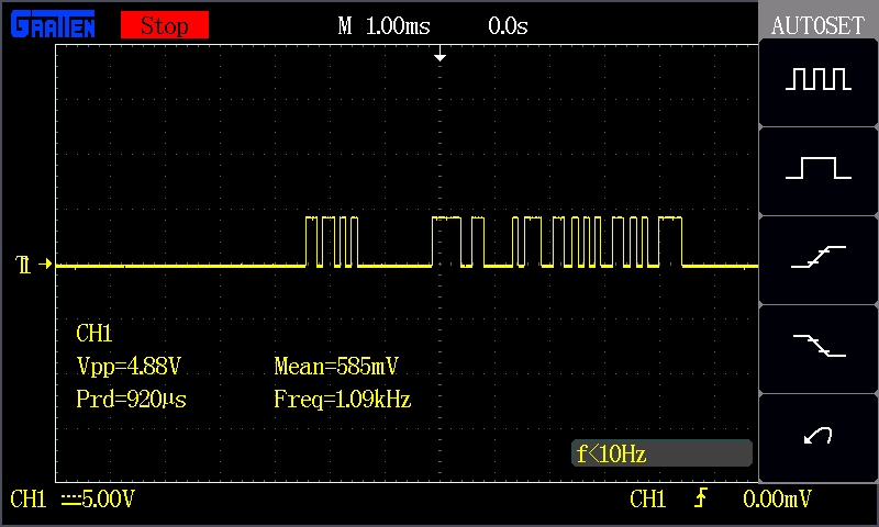
Out of curiosity, I decided to do some tests to verify this serial output before connecting it to a UART. After quickly soldering some male header pins to the sensor, I powered it using a 5V FTDI and jumper wires. I tried placing a multimeter between Tx and GND to see if the output would be somewhere around 5V. I was only reading about 0.29V to 0.30V. This did not seem useful since the serial output was too fast for my multimeter read. I then decided to connect an oscilloscope probe between Tx and GND. Zooming out, I could see that the output was 5V when powering the Vcc pin with 5V:
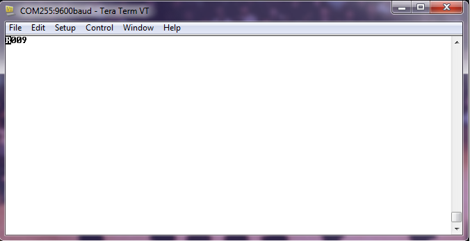
Satisfied, I decided to connect the sensor's Tx to the FTDI's Rx and read the output through a serial terminal. I used Tera Term to configure the serial terminal (9600 baud, 8 bits, no parity, and one stop bit) as the datasheet stated. Unfortunately, my output made no sense:
[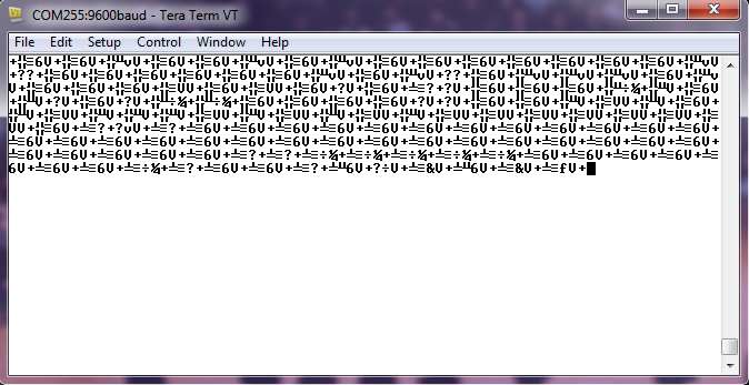
I had the correct baud rate, so it was not a baud rate mismatch. I then remembered that RS-232 had a characteristic of being an inverted signal! I had a few ideas for approaching this problem. In my solutions, I discovered the ultrasonic range finder's output had a combination of RS-232 (an inverted signal) and TTL (voltage range between 0V up to 5V) as the datasheet stated. To distinguish this output from the other two, I decided to call this an "inverted TTL" signal. Other sources might call this a "signal inversion" or an "inverted TTL-level signal."
Solution 1: Inverting a Signal Using an NPN Transistor
Using my knowledge of transistors and the concept of logic gates, I decided to build a NOT gate to flip the signal on a breadboard. Luckily, I had a 2N3904 NPN transistor from the SparkFun Beginner Parts Kit and a few 330Ω resistors on my desk. For protection, I added one 330Ω resistor before the base of the NPN transistor and a second 330Ω resistor on the high side before the collector. The collector was connected to the RX of my FTDI. Here's a quick diagram of the circuit that I used:
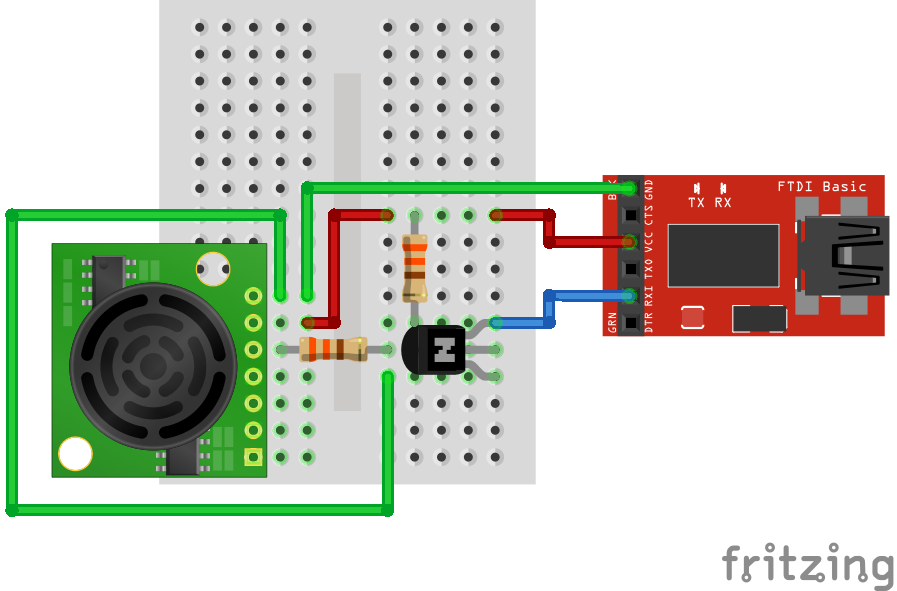
Having a hard time seeing the circuit? Click on the wiring diagram for a closer look.
Note: Depending on the specs of your transistors, you may need to adjust your resistor value. The 330Ω resistor was sufficient enough in this circuit.
After building the circuit on a mini-breadboard, I connected it to my computer.
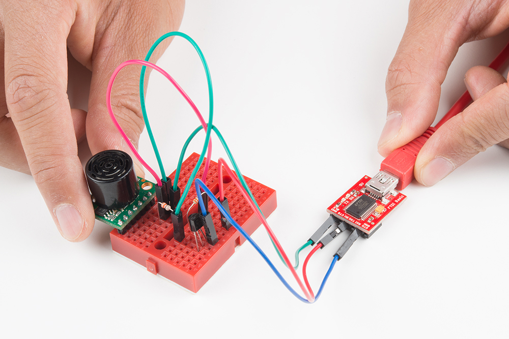
Opening Tera Term again, I started receiving coherent sensor data as expected as I moved an object in front of the sensor!
Solution 2: Inverting a Signal With Arduino's Software Serial
I was curious whether there was a way to read this "inverted TTL" signal without the transistor and resistors. Theoretically, it should work with some code since the output just needs to be flipped. Looking online, I eventually discovered that Arduino has an extra parameter that easily flips your serial data! If you have an Arduino (i.e., RedBoard or Arduino Uno - R3), you can connect the ultrasonic sensor's UART to an Arduino's software-defined UART.
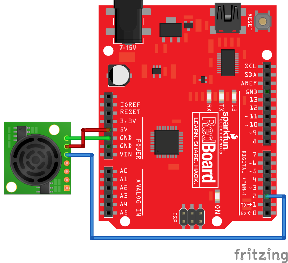
Having a hard time seeing the circuit? Click on the wiring diagram for a closer look.
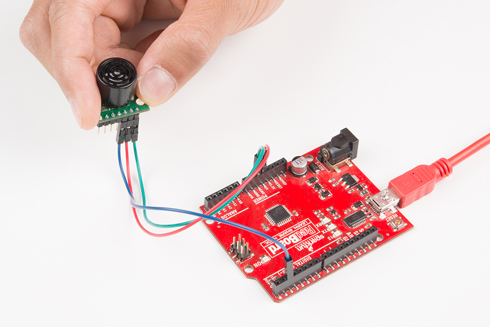
After connecting the sensor to my Arduino, I connected it to my computer.
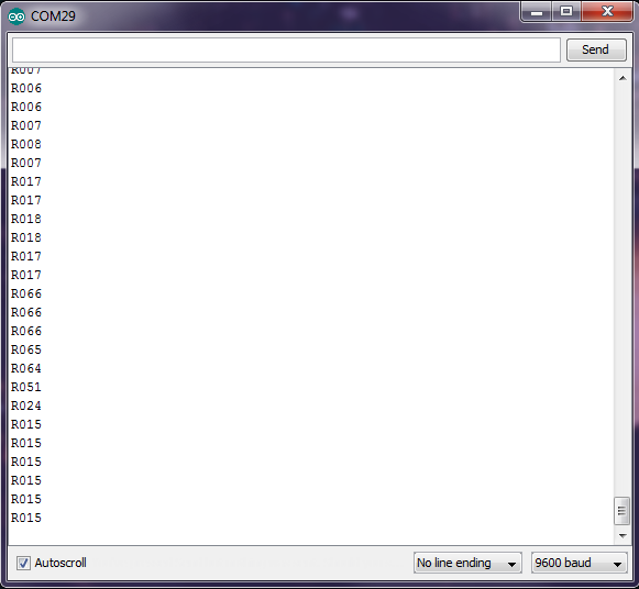
By defining the software serial UART and setting the third parameter as true, the signal would be inverted back to normal. I decided to add this parameter in a basic serial pass-through code that is used in a few of our hookup guides. By opening the Arduino serial monitor, I was able to read the sensor data as expected. However, it was a bit hard to read. I decided to add a few condition statements to print data on each line.
Conclusions
If you ever run into this issue where the serial output is not your standard RS-232 or TTL from a Tx pin, it might be an "inverted TTL" signal that might require a basic NOT gate or some additional code to read. Always make sure the voltages are safe before connecting the serial device to your system. I hope you enjoyed my not-so-trivial tech support problem and how I helped the customer out. Until next time!
Resources and Going Further
For more information, check out these resources below:
- Switches – Digital Logic | Inverter
- Logic NOT Gate
- Serial Communication
- RS-232 vs. TTL Serial Communication
- Serial Terminal Basics
- Arduino: Software Serial Constructor
- ASCII
- Data Types
- Maxbotix MaxSonar Ultrasonic Sensor Fritzing Part
- Enginursday Ultrasonic Range Finder GitHub Repository
Going further, I converted the serial output into a decimal value. I also verified the data using an array. This is useful if you want to do more with the serial output:
If you are using a Raspberry Pi, I also happened to find some example code using a PNP transistor from Simon Monk:


RS-232 - One of the most non-standard standards ever invented. :)
This is an old hack. Back before charge pump style RS232 chips were a thing, you needed a -5 or -12V supply for your RS-232 driver. The MC1489 receiver chip (your grandpa's 232 RX chip) would work with a signal that went between 3V down to about 1V (it only need a plus rail and ground) so you could drive an RS232 input with a TTL gate and save having a negative supply rail. I believe most of the newer RS232 chips work the same way as the MC1489. The hack won't work under all conditions a real 232 driver will, but for bench stuff over a few feet with a known receiver, it works fine.