- Home
- SparkFun OpenServo

SparkFun OpenServo
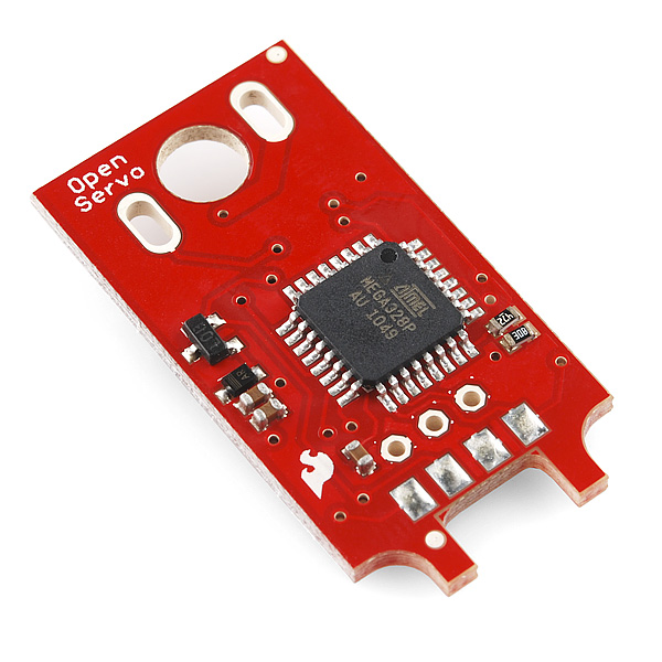
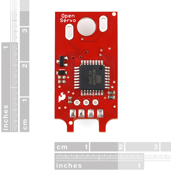
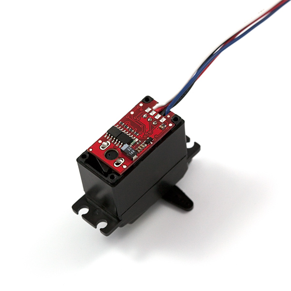
This is our version of the OpenServo open-source servo controller board. It's meant to replace the existing controller board in any standard servo (~.78 inch servo width). With this board you can control a servo entirely with I2C/TWI commands rather than PWM, meaning that multiple OpenServos can be controlled with just two lines! The OpenServo firmware also offers some interesting control features, such as querying a servo with an unknown position, setting control gain discretely and on-the-fly, and even querying the destination of the actuator before it reaches it!
SparkFun OpenServo Product Help and Resources
Core Skill: Soldering
This skill defines how difficult the soldering is on a particular product. It might be a couple simple solder joints, or require special reflow tools.
Skill Level: Noob - Some basic soldering is required, but it is limited to a just a few pins, basic through-hole soldering, and couple (if any) polarized components. A basic soldering iron is all you should need.
See all skill levels
Core Skill: Robotics
This skill concerns mechanical and robotics knowledge. You may need to know how mechanical parts interact, how motors work, or how to use motor drivers and controllers.
Skill Level: Rookie - You will be required to know some basics about motors, basic motor drivers and how simple robotic motion can be accomplished.
See all skill levels
Core Skill: Programming
If a board needs code or communicates somehow, you're going to need to know how to program or interface with it. The programming skill is all about communication and code.
Skill Level: Competent - The toolchain for programming is a bit more complex and will examples may not be explicitly provided for you. You will be required to have a fundamental knowledge of programming and be required to provide your own code. You may need to modify existing libraries or code to work with your specific hardware. Sensor and hardware interfaces will be SPI or I2C.
See all skill levels
Core Skill: Electrical Prototyping
If it requires power, you need to know how much, what all the pins do, and how to hook it up. You may need to reference datasheets, schematics, and know the ins and outs of electronics.
Skill Level: Rookie - You may be required to know a bit more about the component, such as orientation, or how to hook it up, in addition to power requirements. You will need to understand polarized components.
See all skill levels
Comments
Looking for answers to technical questions?
We welcome your comments and suggestions below. However, if you are looking for solutions to technical questions please see our Technical Assistance page.
Customer Reviews
No reviews yet.
Lots of dead links on this ancient project. The best resource I've been able to find is the github repo here: https://github.com/ginge/OpenServo
From the schematics it looks like your version of these boards is based on the OpenServo V2 branch. Out of curiosity, what made you decide to go for that version, instead of V3?
This is a bit confusing - if I'm creating a custom "servo" using a DC motor and slide pot, I presume that I have to first program it to correctly control the motor using the slide pot input.
Can this programming be done over I2C via an Arduino for example? Or do I need some special AVR plug-in programming unit, and if so, which one?
I have read a lot of negative messages in this thread about the OpenServo board.
Question: Is this board ready to use? (no firmware update, nor compiler,....)
And in case of "this part is useless".....is there any alternative out there? Best in combination with OpenEncoder and 360° rotation.
Grettings
Andreas
HEADS UP! This board is SERIOUSLY underrated here. And here's the reason why: SparkFun ships these boards with the fuses set all wrong. The internal clock divider is enabled so out of the box the Atmega328P on this controller is running at only 1MHz where as it should be running at 8MHz. Actually none of the fuses were set right out of the box. Correct fuse settings for this controller are as follows: hFuse:D9 lFuse:E2 eFuse:04. You can use your Arduino Decimilia, FTDI-breakout board, or any AVR compatible programmer to set the fuses. Google for AVRdude and AVRdude GUI (and if you're using your Arduino/FTDI-breakout you'll also need the FTDI bitbang patch for AVRdude.
Please note that the fuses recommended on the OpenServo Step-by-step-guide are meant for Atmega168 so they're wrong as well! After setting those fuses right this controller is everything it's supposed to be.
To those who cannot get the servo moving please note that you need to set the PID values first as they're set to zero by default. Also you need to set the PWM_ENABLE byte as well.
@FreeGroup: So, no, this isn't ready to use as is but it's an easy fix. I installed my controllers to two PowerHD 1204 HPs in an octocopter camera stabilizer and haven't had any problems once I found the correct PIDs.
@SparkFun: No wonder you're not selling too many of these as the support is really poor and you're shipping them with wrong fuse settings out of the box!
-Sami
I think the hFuse value needs to be DA, not D9 (BOOTRST bit cleared, BOOTSZ0 bit set) in order to use the OpenServo boot loader (i.e. MCU starts at address 0x3c00 instead of 0x0000 when coming out of reset).
Has anyone checked out the ZCT1009FTA? I was wondering who makes it and were I could find the data sheet for it? The only thing I have found on Google for ZCT1009 is a set of towels from China OR ZCT100 which turns out to be a tilt meter. I knew that SparkFun was creative but I did not realize they were that creative.
Try ZXCT1009FTA instead.
- Dean
Has anyone else had problems selecting suitable gains for the openservo, The servo either overshoots or has lots of steady state error. Also Integral control does not appear to work, the motor does not move with just integral control. I am using the pre loaded firmware
Yes!
Please if anyone has gains that work with the "TowerPro" servo that sparkfun sells please post them. The only 'kind of' suitable parameters I've found is P-200 D~240, but as AK47 said, that leaves huge steady state error. Also MAKE SURE TO SET "SWAP_PWM_DIRECTION_ENABLED" or your servo will try to destroy its self.
Sparkfun, please a little support on this one, and please "Release" your CVS code module before you zip it up for the public.
I have tried with 3 different servos (high torque metal gear, $2 micro servo and some standard plastic gear servo) and had the same outcome with all 3. Huge offset from desired location with gains of P300 D600, or massive out of control oscillations with P600 D2000. Integral control is what is really needed but it still does not appear to work. Derivative control only makes the control worse above about 800 (suspect its due to increased noise when taking derivative). Any help would be much appreciated.
You should look up PID tuning techniques to properly tune the servo control loop in your application. A good linear controls textbook is your friend. The Ziegler?Nichols method is the most commonly used for PID systems, but PD systems are easily tuned by hand.
Here is a simple method of manually tuning a PD controller: Set the derivative gain to zero, slowly increase the proportional gain until you get oscillations, then start increasing the derivative gain until the oscillations stop. If you want, you can increase the proportional some more and compensate with more derivative, but you will get diminishing returns and more jerky motion at some point. Also as d3smo said make very sure your signs/directions are right before increasing the gains too much.
Note that unless there is a constant load (torque) on the servo, any integral term will only mess it up (with delay and overshoot). That is because integral terms are only needed when a nonzero input (motor voltage) is required to have a stationary output, like in an oven, but that is clearly not the case for an unloaded servo. Increasing the proportional gain is the only way to remove steady-state error in this kind of system. I learned this the hard way with my own servo mechanism long before my first control theory class.
The stability of a positional control system is inherently dependent on the nature of the load. Frictional losses will improve stability and inertia will reduce stability. If the control system is proportional only the control signal approaches zero as the system approaches the set point position. If the system has significant inertial it will overshoot and the control signal to drive it back will initially be very small. If velocity feedback is added the control signal can start breaking the movement of the system as the signal proportional to the error becomes small. This helps to avoid overshoot. Qubix mentions that the v2 system does not have sensors for "back EMF" which could be used to provide velocity feedback (the "back EMF" is proportional to the speed of the motor). The derivative of PD control is somewhat different than velocity feedback in that it is the derivative of the error rather than the speed of the motor. From a math point of view derivative of position is the same as velocity but the derivative of the error also includes changes in setpoint. In practice an actual velocity signal is better than calculating the derivative of position because change in position is small and needs to be amplified resulting in a very noisy sometimes useless signal. The back emf from the motor is large. It can also be affected by noise spikes but spikes contain only very high frequencies that can be filtered from the signal. The bottom line is that for practical reasons it would be best to use proportional control with velocity feedback (in this case in the form of sensing the back emf). The typical analog RC servo does sense the back emf so if version two does not it is at a significant disadvantage in comparison.
Why doesn't anybody offer an OpenServo board pre-attached to a servo? Maybe at few different servo models of various strengths?
This would directly compete with CrustCrawler's AX and RX offerings, at a lower price point and offering hardware compatibility with existing servo hardware (brackets etc). I would buy it.
It notes that you can control via I2C and control multiple servos with just two lines. That sounds great, but what is the maximum number of OpenServos that can be chained together?
Hey Guys has the fuses on this unit been fixed now ? do they work correctly as supplied by spark-fun
SparkFun is so frealing cool!
Why do you use the more expensive atmega168 when you could use something like the attiny2313 or atmega48 and lose a lot of the cost?
Sometimes it's code size that's the restriction. The smaller pin-count parts have less RAM and ROM than the larger parts.
I'm not sure what the original decision was behind using the atmega168, but we are currently looking into revising this board, so hopefully there will be some kind of update to the controller in the near future.
How's the revision on this board coming?
It just got transferred to one of our new engineers, so it is currently in the works. Still probably a month or two out, but it is being worked on!
Any chance of having a magnetic encoder option as in http://letsmakerobots.com/node/18615 ?
I added the suggestion to the bug regarding this revision. Hopefully they take it into consideration.
Bump. I am curious about an update to this.
It's still on the list, but unfortunately got bumped to a lower priority due to some collaborations that cropped up. Hopefully the revision will be addressed soon.
Any update on a new revision of this board? Our team is VERY interested in this board, especially if the bugs are worked out and the controller is potentially simpler/cheaper. We need to order a LOT of them - 400+ units if possible (not sure if there are additional discounts for extra large volume orders?)
One of our engineers has started the research for major improvements on this board. It is still in development though.
Bump! really looking forward to the new refined version!
Check out the replacement here
Any news? As many others, I would be very interested by an openservo board. I'm building a 4DoF hexapod, with TowerPro MG996R. These servos are great (and cheap), but not made for robot slow moves. I made some quick tests with an external regulation, using Arduino and H-bridge, and is is easy to tune a PID for this kind of usage...
FYI it is hard to find the high side current sense IC because the schematic label is not the manufacturer part number. ZXTC1009 datasheet http://www.diodes.com/datasheets/ZXCT1009.pdf . I believe is the chip or its equivalent.
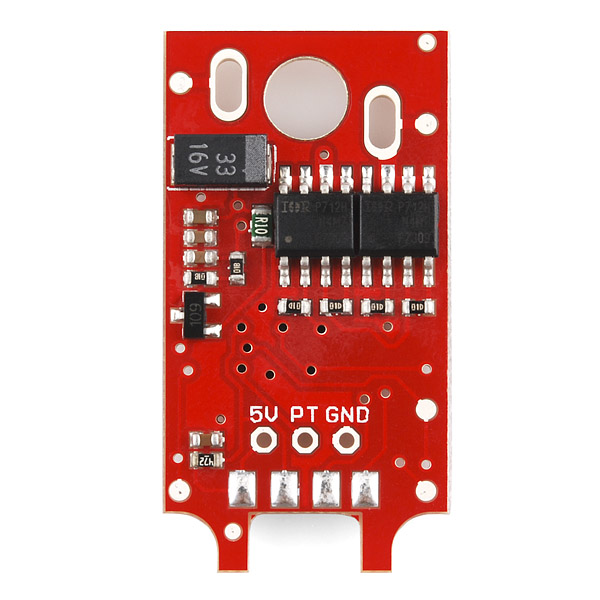
How do i hook this up to an Arduino? I understand that i can communicate serially, but the board is not labeled. Are the four pads at the bottom where wires go? From the last picture the wires are blue, black, red, white. Tx, Gnd, +5, Rx? Thanks for any help, I'm sure i'm missing something obvious.
is it the same as http://www.openservo.com/OpenServoPinout#Pinout_configuration_for_the_1.x_and_2.x_OpenServo_connector. SCL, Gnd, +5, SDA Using I2C?
After a few months of trying to get this to work i can say that it takes a huge amount of time to get it working and when it does it is still worse than a normal servo with regards to precision. Save yourself some time and use a normal servo instead.
Just got three of these but...
Installed it to Futaba 3010-servo, controlling it with PIC18F2550 (working i2c master).
Servo acks every command I send but does not move.
If I try to read something from servo, it always returns 255.
Any ideas what could be wrong?
I'm having the same issue. I've installed it into a VEX servo and the install went very smoothly. It is responsive on I2C and I'm able to read and write all the registers. I can read the position which changes if I manually move the servo, so I know that the logic and potentiometer are working. I'm feeding it 9VDC, which is about right for the motor, but I get no hint of movement.
Oh, I verified the motor works by giving it some juice before soldering openservo in place, so I know it isn't a dead motor. I also tried sending it command 0x82 (PWM_ENABLE), but that didn't help.
Has anybody else had (and resolved) this issue?
Ok, just got some of those devices. To start a list of servos suitable for this product: this version of the OS v2 can NOT be installed into a Hitec 645 MG, simply because the motor is too tall. I may be wrong, but it appears that the area of the PCB occupied by electronic components is larger, compared to the v2.1b PCB posted on the openservo web-pages (here: http://www.openservo.com/PrintedCircuit2). In particular, the Mosfets and the 33uF capacitor (C8) are closer to the motor contacts.
Looking at the photographs on your web-pages it seems that your PCB can be installed into a TowerPRO SG-5010. Any other servo, maybe something comparable (considering torque) to the 645 MG?
No offend meant, and best regards.
Does this come flashed with the bootloader and application?
If you put two equal resistors on the potmeter pads, it should be possible to use a DC motor. I would not use large DC motors though, because I'm not sure how much current the H-bridges can supply.
The good news though is that you must power this board with more than 6V. There's an internal 5V regulator for the logic, but the motor is powered by the raw input.
Can I stick this on a DC motor instead of a servo?
Great to see these. I've been following this project for a while. Pity they don't seem to have the back EMF sensors like v3, would have been sweet. Also a proper datasheet would be nice.
Note: The firmware link currently points to the example control code.