- Home
- Product Categories
- Monochrome
- Serial Enabled 16x2 LCD - Yellow on Blue 5V

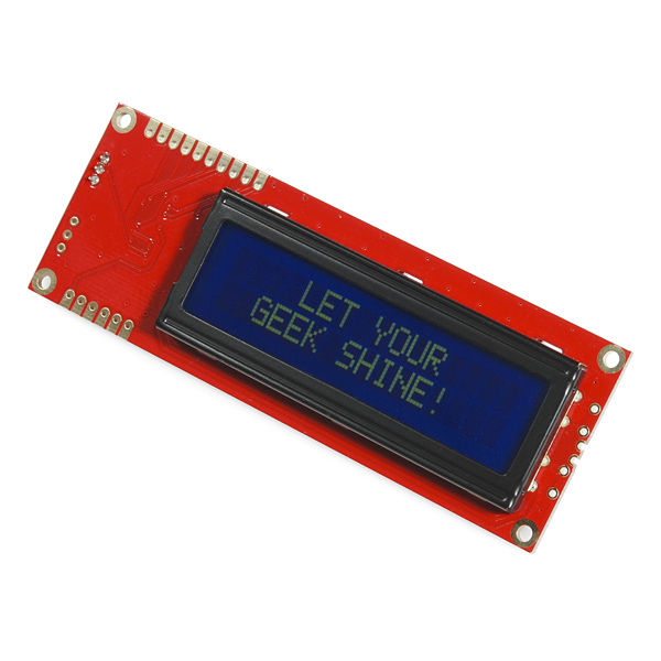
Serial Enabled 16x2 LCD - Yellow on Blue 5V
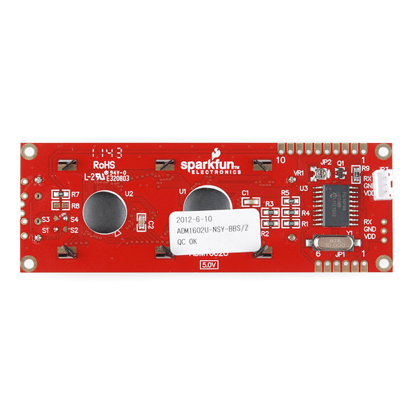
This is the latest evolution of our serial LCD. Included on a single board is a 16x2 LCD and an embedded circuit based around a PIC 16F88. The on-board PIC takes a TTL serial input and prints the characters it receives onto the LCD. The installed firmware also allows for a number of special commands so you can clear the screen, adjust the backlight brightness, turn the display on/off, and more.
Communication with SerLCD requires 5V TTL serial at a default baud rate of 9600bps (8-N-1). You can adjust the baud to any standard rate between 2400 and 38400bps. The power (VDD), ground (GND) and RX pins are all broken out to both a 0.1" pitch header as well as a 3-pin JST connector.
SerLCD has the ability to dim the backlight to conserve power if needed. There is also a potentiometer on the back of the display to adjust the contrast.
This LCD makes for a great gift, because it can be used for so many different projects! For more gift ideas check out the SparkFun Gift Guide!
Replaces:LCD-00814
- Embedded PIC 16F88 utilizes onboard UART for greater communication accuracy
- Adjustable baud rates of 2400, 4800, 9600 (default), 14400, 19200 and 38400
- Operational Backspace
- Greater processing speed at 10MHz
- Incoming buffer stores up to 80 characters
- Backlight transistor can handle up to 1A
- Pulse width modulation of backlight allows direct control of backlight brightness and current consumption
- All surface mount design allows a backpack that is half the size of the original
- Faster boot-up time
- Boot-up display can be turned on/off via firmware
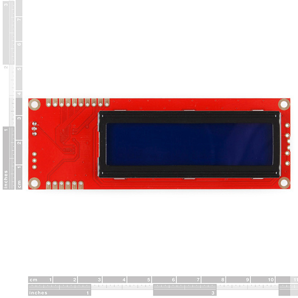
- User definable splash screen* PCB: 103x36mm
- LCD: 71.4x26.4mm
Serial Enabled 16x2 LCD - Yellow on Blue 5V Product Help and Resources
Core Skill: DIY
Whether it's for assembling a kit, hacking an enclosure, or creating your own parts; the DIY skill is all about knowing how to use tools and the techniques associated with them.
Skill Level: Noob - Basic assembly is required. You may need to provide your own basic tools like a screwdriver, hammer or scissors. Power tools or custom parts are not required. Instructions will be included and easy to follow. Sewing may be required, but only with included patterns.
See all skill levels
Core Skill: Programming
If a board needs code or communicates somehow, you're going to need to know how to program or interface with it. The programming skill is all about communication and code.
Skill Level: Rookie - You will need a better fundamental understand of what code is, and how it works. You will be using beginner-level software and development tools like Arduino. You will be dealing directly with code, but numerous examples and libraries are available. Sensors or shields will communicate with serial or TTL.
See all skill levels
Core Skill: Electrical Prototyping
If it requires power, you need to know how much, what all the pins do, and how to hook it up. You may need to reference datasheets, schematics, and know the ins and outs of electronics.
Skill Level: Competent - You will be required to reference a datasheet or schematic to know how to use a component. Your knowledge of a datasheet will only require basic features like power requirements, pinouts, or communications type. Also, you may need a power supply that?s greater than 12V or more than 1A worth of current.
See all skill levels
Comments
Looking for answers to technical questions?
We welcome your comments and suggestions below. However, if you are looking for solutions to technical questions please see our Technical Assistance page.
Customer Reviews
No reviews yet.
Check the wiki for the HD44780. The chip supports commands that aren't mentioned in the datasheet.
James
Is there a way to get inverse video on these ? It's very handy for drawing menus, but I can't seem to find a command to do this.
Does anyone have this working with the chipKIT Uno? The chipKIT has 5v and 3.3v available, but the logic level outputs are at 3.3v. Will this display work if powered at 5v and driven at 3.3v? Is a 3.3v to 5v level shifter required? The 16F88 spec indicates that a "HIGH" can be as low as 2.0v or 0.8v on a schmitt trigger input.
It would be nice if this backpack also supported I2C and SPI like the Serial LED product does.
Update1: Working fine with chipKIT UNO. No problems seen with the 3.3v logic level. No level converter seems to be needed.
Update2: Code posted on http://www.chipkit.org/forum/ Topic: "Sparkfun Serial Enabled 16x2 LCD - LCD-09396"
James
I've been messing around with this screen all day. It's finicky, but now that I got the hang of it I think it's pretty good. So I figure I would post my noobish comment.
First and foremost just because the JST connector on the screen says RX does not mean that's the pin it suppose to be hooked too. I don't know if that was obvious to everyone else or not. Anyways I used pin 13 and I have an Arduino uno r3.
Second, Kamiquasi(the guy that posted above me) linked the page below.
http://arduino.cc/playground/Code/SerLCD Get the code on the first page, then click on serLCD() under functions and copy that code too. That will get you running.
lastly the datasheet listed for this lcd screen is quite useless. It lists all the commands, but is confusing. Even if you cannot get the code above working use it as a manual. It shows ever command and how to write it to the screen using hex.
I have been programming for years in various languages and I have to say the Aruduino is very nice environment. It doesn't get as angry as PIC's do. Next to labview it's one the only environment that has errors that are in English and actual help solve the problem. The Sparkfun community is awesome. I do know how many questions I have had that have been answered by these comments so I figured I would post my findings.
How can I turn on the backlight using Arduino? does it need extra power wiring?
From the datasheet: "By sending the special command character 0x7C (decimal 124) followed by a number 128-157, the backlight PWM value will be set". Above that is a little table that shows that: "128 = off 140 = 40% on 150 = 73% on 157 = 100% on" Shouldn't be a secondary power source required for the LCD.
I did it but it didn't work, All other commands works using 254 code folowd by other commands (like clean, move cursor,turn display on and off,....)
is there any sample code for arduino to check it out? Thank you
Have you looked at this page? http://arduino.cc/playground/Code/SerLCD
Thanks for the Info, I used that library too, got the same result, it look like the screen LEDs not good (I can barly see the backlight even with highest setting (lcd.setBrightness(30)). Thanks for your help.
I am using the serLCD v2.5 with a PicAxe18X, and I found a little hint to help rid of the first character or command jibberish in the PicAxe docs under SerOut command:
Also I felt a bit dumb after I realized that the 0xFE command prefix is used for the Extended Commands, not the 0x7C used for the hardware set-up. Doh!
This is a test snip that seems to work: (Thanks to JPLofLIL for the jump-start.)
Can you please post a correct schematic and source code?
This LCD worked well for me until it failed at about 5 hours run-time. I'm not very experienced with the Picaxe 18M2 but this program works for me . . . No responsibility accepted etc.
pause 200
setfreq m8 'needs to be fast enough for higher baud rates
pause 1000
serout C.3,T9600_8,(0x7c,150) 'backlight values 128-157
pause 1000 '128=off 140=40% 150=73% 157=full on
'-------------------------------------------------------------------------------
'NOW SETUP DISPLAY FOR FIRST TIME (then stored in EEPROM)
serout C.3,T9600_8,(0x7c,4) 'display 16 wide =4
pause 200 'display 20 wide =3
serout C.3,T9600_8,(0x7c,6) 'display 4 lines = 5
pause 200 'display 2 lines = 6
'-------------------------------------------------------------------------------
serout C.3,T9600_8,(254,$01) '254 to send command - 01 clears display
Pause 30 '30 is the minimum lag required for command to take effect
'254,8 Hide display
'254,12 Restore display
'254,128 Move to line 1, position 1
'254, y Move to line 1, position x (where y = 128 + x)
'254,192 Move to line 2, position 1
'254, y Move to line 2, position x (where y = 192 + x)
main:
serout C.3,T9600_8,(254,128) 'cursor to line 1 position 1
pause 200
serout C.3,T9600_8,(" Hello !")
pause 200
serout C.3,T9600_8,(254,192) '192 to goto start of line 2
pause 200
serout C.3,T9600_8,(" Line 2")
pause 2000
serout C.3,T9600_8,(254,$01) 'clear display
pause 200
goto main
I have ported LiquidCrystal library for use with the serial LCD you can look at my code here. Still working on finishing all the documentation. But putting up for now hopefully someone will find it usefull.
http://arduino.cc/playground/Code/SerLCD
-Thanks
Can you recommend a work-around for the start bit requirement? I'm trying to interface to a Picaxe 18M2, but it looks like the inability to send a start bit is preventing it from working correctly. I think its triggering off the first bit it sees, so only some characters are properly shown.
This display has worked well for me! I wish a current schematic were posted, so I'd know what the connections on the edge of the board are. There are 6 pads on the bottom and 10 on the top of the board. Basically right now I'd just like to make the RX, Vcc and GND connections via standard 0.1" headers if available there, but it'd also be nice to know what the rest of the connections are just in case there's other coolness available.
I love these. I use one in pretty much every project just because it's so useful for development and for making user interfaces. I wish the serial interface supported modifying the character set--this would enable a bunch of fun uses outside of just displaying text. From the LCD datasheet it seems like this is possible (at least there are commands for writing to CGRAM). Any hope?