- Home
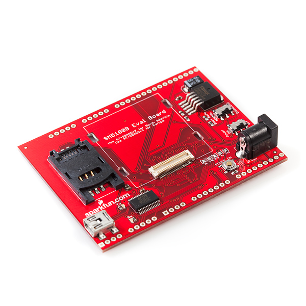
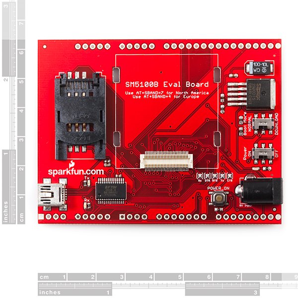
- SparkFun SM5100B Evaluation Board

SparkFun SM5100B Evaluation Board
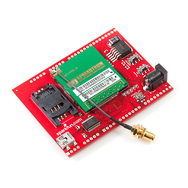
This is an evaluation board for the SM5100B GSM/GPRS module; everything you need to get started with the cellular module is included on this board. With FTDI's FT232RL connected up to UART0 of the SM5100B you can send AT commands from a PC terminal straight to the module.
This board comes as shown in the picture with the 60-pin SM5100B mating connector, SIM card socket, SPX29302 3.8VDC high-current voltage regulator, FT232RL USB-to-UART, Mini-B USB connector, and more supporting circuitry. The SM5100B module is not included.
Note: If you don't want to use your computer, or the USB to communicate with the SM5100's UART, make sure you clear the RX, DTR, RTS, TX, and CTS jumpers.
- 60-pin SM5100B mating connector populated on board
- Power from barrel jack regulated to 3.8VDC
- SM5100B UART0 connected to FT232RL UART-to-USB chip
- Mini-B USB connector integrated
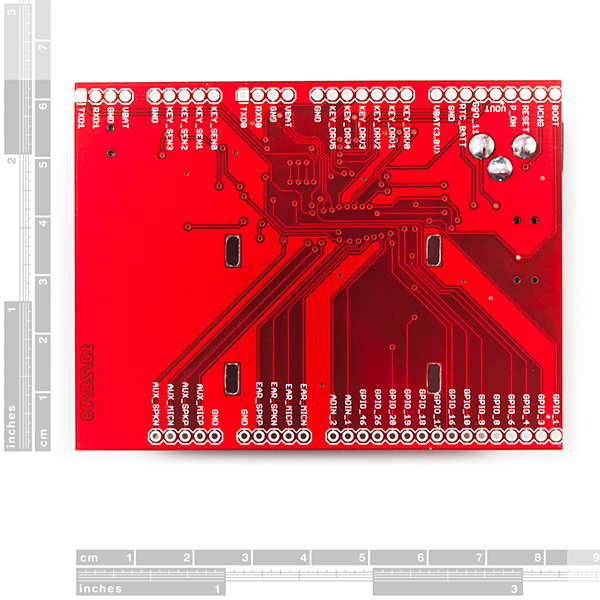
- All pins of the SM5100B broken out to 0.1" pitch headers
- SIM socket integrated with SM5100B and populated on-board
- ON/OFF and Boot mode SPDT switches
- POWER ON momentary push-button switch
- Red power indicator LED
- RX, TX LEDs
- 3.2 x 2.5"
SparkFun SM5100B Evaluation Board Product Help and Resources
Core Skill: Soldering
This skill defines how difficult the soldering is on a particular product. It might be a couple simple solder joints, or require special reflow tools.
Skill Level: Rookie - The number of pins increases, and you will have to determine polarity of components and some of the components might be a bit trickier or close together. You might need solder wick or flux.
See all skill levels
Core Skill: Programming
If a board needs code or communicates somehow, you're going to need to know how to program or interface with it. The programming skill is all about communication and code.
Skill Level: Competent - The toolchain for programming is a bit more complex and will examples may not be explicitly provided for you. You will be required to have a fundamental knowledge of programming and be required to provide your own code. You may need to modify existing libraries or code to work with your specific hardware. Sensor and hardware interfaces will be SPI or I2C.
See all skill levels
Core Skill: Electrical Prototyping
If it requires power, you need to know how much, what all the pins do, and how to hook it up. You may need to reference datasheets, schematics, and know the ins and outs of electronics.
Skill Level: Rookie - You may be required to know a bit more about the component, such as orientation, or how to hook it up, in addition to power requirements. You will need to understand polarized components.
See all skill levels
Comments
Looking for answers to technical questions?
We welcome your comments and suggestions below. However, if you are looking for solutions to technical questions please see our Technical Assistance page.
Customer Reviews
No reviews yet.
So for the record, there needs to be better documentation on just using this board by itself. No Adruino... Just the USB port it comes with.
Here's a few tips that would have saved me some time.
1. Start with the power switch off.
2. Plug in the USB cable and make sure windows recognizes it as a com port.
3. Plug in a separate power source to the barrel jack that can handle the 2 amps that might be drawn.
4. Using a terminal program connect to the new COM port using a BAUD rate of 115200... 8 data bits -- no parity -- 1 stop bit.
5. Turn the power switch on.
At this point I get 5 groups of garbage and then it starts speaking intelligently with SIND messages updating me on it's progress in connecting to the network.
SIND 11 is the one to watch for that typically says it's connected and ready to go.
-Patrick
Patrick,
You nailed it! I powered up exactly that sequence and it works for the first time ever!! The documentation on this module and this board sucks beyond belief. Thank you for writing this down.
I wasted a lot of time trying, unsuccessfully, to use a Tmobile SIM card. It was stuck in a continuous reset looop. So I got an AT&T card and it no longer reset itself but it would not connect. Your tip has allowed me to connect and make voice calls and to send SMS.
I'm no longer stuck!! Thanks to you!!
Mike
Oh and TimB44 was right with the "AT+SBAND=7" command.
After I got the terminal connection to work I had to send that with a before the chip would connect. It seems to remember that setting now though. I dont have to send it every time I start it up.
-Patrick
Thanks for letting me know Mike.
I took the time to comment out of shear frustration, but now I'm glad it actually served a purpose.
I think part of the problem is that they link to a tutorial that uses a different board. The tutorials board looks like an actual arduino compatible shield. I have to be honest in that I thought this was one of those when I bought it, but that was my fault I guess for not looking closely enough at the picture in the tutorial.
My card is a TMobile and it's working so I must have gotten lucky. Probably good that I did, cause as frustrating as it was without SIM card trouble I would have straight lost it, lol. I still have no idea on some of the garbage I get as soon as I turn it on, do you get that?
-Patrick
I see different things written in different places. Should it be connected at a BAUD rate of 115200 or 9600?
Hello, I bought 2 of these for the prototype I am working on. I am trying to connect the ev board to Arduino. Could you please clarify what do you mean by "clearing the RX, ... jumpers ". Do I need to desolder them from the board? Thank you!
Hi, Does anyone know if this evaluation board and the part itself will be enough to connect it to Arduino. Or do I also need a shield? Thanks
We recommend either the shield -or- the evaluation board. Both will allow you to hook up to the Arduino, though you can simply connect the evaluation board to your computer via usb.
Thank you for replying,
I am now trying to connect the ev board to Arduino Due. Do I just connect the pins RXD1, TXD1, GND of the evaluation board to TX, RX, GND of Arduino?
P.S. I am powering the device externally through the barrel.
Thank you again, I really appreciate it!
Yup, that should work!
I have this board, and I cann connect to GSM but not to GPRS. The attach command AT+CGATT=1 always sens error CME ERROR:0 phone failure. IT SEEMS I NEED to UPDATE the firmware for the spreadstrum modem. I called spreadstrum and they asked me to contact sparkfun.
This board definitely needs a mounting option (i.e. 4 mounting holes - one at each corner). How are people mounting this board in their projects?
To all sparkfun users, we would like to offer our experience. We were using a AT&T "go-phone" (pay as you go) sim card purchased in Arizona, USA. We too had a lot of trouble learning how to interface with the device. This is what worked for us:
If anyone is interested in getting in interfacing this module with the Beaglebone Black, follow this link: beaglephoneblk.wordpress.com
I am having no luck getting this on the network here at all. I have the previous version of the cell breakout board that Sparkfun sold based on the ADH8066 module and that works great with the same SIM and the same antenna and the same power supply. But when those 3 things are moved to the new board I never get joined on the network. The signal strength is always 0,99 and I never get the +SIND:11 message that would indicate that I’ve joined. SBAND is set to 8 as indicated, but I’ve also set it to 7 since someone in the comments above suggested that and when that didn’t work I worked my way through them all from 0 to 10. Rebooting the board each time and never getting an SIND:11 message. The rest of the communication to the host works fine, all the SIM commands work fine, but I cannot actually join the network. Lastly I’ve now twice desoldered, cleaned and restripped the antenna cable and re-soldered it but that hasn’t made any difference either. Lastly I just sacrificed another spare pigtail and soldered it in place on the board but I still can’t get a SIND:11 or do anything on the network.
Any suggestions for a next step? Are there init commands other than the SBAND that I’m somehow overlooking in the docs? I can’t set the COPS or anything until I actually join the network as far as I can tell.
The schematic is wrong ! missed regulator and ftdi chip connections...
Has anyone else experienced a freaze/lock-up behavior in PPP mode? For me after AT+CGDATA="PPP",1 the module seems to be unresponsive. +++ doesn't work to get back to command mode and data doesn't appear to be going back and forth to my connection.
-Zach
The second page of the schematic is missing.
FYI in case someone was wondering, sending CTRL+Z implies sending a byte with hex value 0x1A or decimal 26. The AT command manual say either CTRL+Z or ESC (hex 0x1B I think) should work, I have only been able to get CTRL+Z to work.
Thank you for pointing that out!!
From sweden here. When i start i get this:
~~~~~ +SIND: 1
+SIND: 10,"SM",1,"FD",1,"LD",1,"MC",1,"RC",1,"ME",1
+SIND: 3
+SIND: 4
+SIND: 8
I try to send AT but i dont get any response?!
Can anyone tell me the power consumption while using GPRS? I’ve searched all the documents I could find, but with no luck.
Can anyone tell me the power consumption while using GPRS? I’ve searched all the documents I could find, but with no luck.
This board is using SPX29302 so the input voltage can be up to 16V, but the print on the PCB says 5V. Where is the truth? Can I use 12V input safely?
The truth is out there.
You are correct that you can use a 12V input safely, but ensure that you're using a power supply that can handle the required current. Our 12V wall-wart is not beefy enough for this board, hence the 5V marking.
Hi! I have the evaluation board and the module, but I'm having trouble connecting it to a net.
As Carnagio said, I used a 115200 baud rate in the Terminal program for connecting the board to the computer. In the tutorials I have read, I saw that I must be replied with 5 lines when powering the module.
In my case, I receive 5 characters of garbage (Just as Carnagio), then two correct lines, which are
+SIN: 1 +SIND: 10, "SM",1,"FD",1,"LD",1,"MC",1,"RC",1,"ME",1
but then the comunication stops, and I receive nothing else, and if I send any AT command, I don't get response.
After those 2 lines, I'm suppose to receive these adittional 3 lines +SIND: 11 +SIND: 3 +SIND: 4
these lines are sent to confirm the connection to my local network, so I think that's the problem. I have the antena connected, so that shouldn't be the problem. I'm in M�xico, working with a TELCEL SIM card.
If anyones can give me a clue of what's wrong, I'll be glad to here it. Thanks in advance
Anyone ever gotten "+CME ERROR: 65536014" ?? I've spent over a year trying to get this thing to work. Sparkfun should just send us all new modules of a different brand. I am unable to express the amount of hatred the mere site of this thing invokes in me.
Here I am in 2016 googling this crazy error I just got from this gsm. I got it while trying to enter sleep mode. I never hoped less that google would find sth. Thanks a lot for posting this! My patience has been tested quite a lot while doing project with this module. But it gets better as you read and learn more about how to avoid and deal with errors. Than comes this guy: +CME ERROR: 65536014 and slaps you in the face.
I fully agree. This module is unreliable and seems to live its own life. I'm trying to use this module to control my Arduino over TCP/GPRS. It works, at least for a few minutes. Then the module resets for no reason. If it loses coverage (even for a couple of seconds) the connection is dropped and wont reestablish without a hard reset.
Example:
AT+CGDCONT=1,"IP","APN"
AT+CGACT=1,1
AT+SDATACONF=1,"TCP","IP-Address",80
AT+SDATASTART=1,1
This works, the module establishes a connection to my server and I'm able to send data back and forth via the SSTRSEND command. Now, lets say I use my GSM jammer to have it drop the connection for a couple of seconds, then it looks like this:
AT+SDATASTATUS=1
+SOCKSTATUS: 1,1,0102,160,148,0 //Says socket still connected... not true
AT+SDATASTART=0,1 //Attempt to disconnect fails
+CME ERROR: 65536014
AT+SDATASTART=1,1 //Attempt to restart the connection returns OK... But nothing happens.
OK
Bottom line: Do not buy this product.
Its important to understand the time delay when issuing commands, If you are getting 6553.. Errors try adding a delay.
Hello, I have the SM5100B Arduino shell, but I am having some troubles with the at+agcat command.
I am in Mexico and I make the connection through Telcel, some times the APN configuration works fine. But lately the at+agcat command takes a long time and returns "GPRS operation failure".
Does anyone have any idea about this problem?, I'm using the APN internet.itelcel.com. Thanks for your help.
hi, I just bought this card. I see you're from México, like me. Did you have any trouble connecting the module to TELCEL's net, I mean, you used the SIM form your cellphone?
I have troubles when I power the module. I made a comment describing my problem, it's at the bottom on the page. Could you help me please? Thanks in advance
Has anyone made the SM5100B actually work in North America?? I'm beginning to have doubts, it seems everyone is having trouble with it.
yes, but still working the details. Which cell service are you using. I struggled for 2 weeks until I discovered I was using the wrong APN for AT&T.
First, make sure on the right band:
cell.println("AT+SBAND=7");
If you are using ATT, here's the command:
cell.println("AT+CGDCONT=1,\"IP\",\"Broadband\"");
Also, see this for a quick test of your setup:
http://tronixstuff.wordpress.com/2011/01/19/tutorial-arduino-and-gsm-cellular-part-one/
Tim,
What document are you using to figure out how to use GPRS with this module? For instance, how did you figure out you needed the slashes? How did you figure out the the APN was "Broadband"?
Thanks for you help! We should all write an app note on this when we get it working.
Mike
I have the 5100B eval board but it won't even wake up. Windows sees it as a USB port when I plug it in. I'm using TeraTerm and the most I ever get out of the unit is a series of 3 garbage characters.
First of all: what baud rate does the terminal emulator (TeraTerm) need to be set for? And where in the Sparkfun or FTDI documentation is this described? I've tried every baud rate with no results. I just get a few garbage characters when I hit the reset button on the eval board. Is the board faulty??
Where is there some overall description of how the eval board behaves?
Mike
I have the SM5100B Evaluation Board.
I inserted a simcard, plus nearly all commands return ERROR.
Example:
AT+SLOG=?
ERROR
Why?
Tks!
I cannot get any of the test format commands to work. ie any command that ends with =? does not work.
However, the read commands work for me. Such as AT+SBAND?
And the commands that have no suffix, such as AT+CSQ seem to work OK.
However, my unit will not change to the North American band. So AT+SBAND=7 returns CME ERROR 0.
What's up with this thing?
In US use SBAND=8
Kyle
These commands do not work with me.
I'm in Brazil, but still I can not log into any network.
The strange thing is that the command:
ATX3DT 89889843; returns OK, but phone not ring!
Alex
Good afternoon Alex, I wonder if you could send sms message here from Brazil, with any phone carrier. I am developing an application and the arduino shield me would be helpful.
-Rafael
What SIM cards work with this unit?
I tried to buy a prepaid AT&T microSIM card for this but they said they could not do that. They said their microSIM cards are only for the subscription based Iphones.
I want to send SMS and email. Only AT&T and Tmobile seem to have email gateways. I have not tried to get a Tmobile SIM card yet.
So has anyone actually used this to send SMS? To send eMail? How did you do it??
Thanks!
Mike
I'm using a TMobile SIM. Not much trouble walking in a just buying the activated card. Without a cell phone they had to call a special phone number to activate it... But other than that, no biggie.
I got the pay as you go account cause I wont have a lot of usage on this thing.
-Patrick
Have you gotten this to work in the US on T-Mobile? If so, what settings do you use.?
I am using this simply with a terminal on a pc right now trying to get this thing to send and receive text messages with no luck. Am using AT&T, the device sees the sim card, but I get no RSSI when checking the signal strength, and have not successfully sent or received any sms messages yet. Please help!
I have the same problem. I have been corresponding with LinkSprite tech support (I've gotten no responses from Sparkfun support people) and the band must be changed to GSM850 for north america. The command is AT+SBAND=7. However, this command returns CME ERROR 0 for me. I do not have a resolution to this problem at this time.
I'm beginning to think this module does not work in North America. Has anyone actually made one acquired from Sparkfun work here in North America???!!???
I'm not 100% sure about prepaid, but with my T-Mobile plan I have been able to walk in and say "I want a SIM card".
I have used to for SMS (my Arduino spammed my boyfriends phone with "I love you."), but I'm not sure if I tested e-mail back then.
SMS AT Commands are on Page 58 of the AT Command Set pdf.
Hi,
can you tell me how you set up your device for a Tmobile SIm.
HAving no luck getting the device regeistered to the network. Freq band is set right.
-Bill
If you set the SBAND to 8 the tmobile cards will work.
Kyle
I have the SM5100B Evaluation Board<br />
I tried to use the H/W serial port in the ardinu but it didn't work, it only work witht he software serial port. I read that their are jumpers tp configure which port to use but couldn't find any jumper in the evaluation board.<br />
<br />
please help me ASAP<br />
<br />
regards,<br />
<br />
<br />
Are you talking about the little solder jumpers on the board that you have to clear if you dont want to use the on board USB port? They are tiny and near the barrel jack port and button.
-Patrick
Any chance of getting the PCB overlay as a PDF?
Would be nice to have mounting holes on the board and maybe usb power supply.
I totally agree on the mounting holes.
USB power supply is impossible though. If this thing tried to draw the rated 2A off your USB port bad things would happen for sure. :)
-Patrick