- Home
- Product Categories
- Kits
- It's a Through-Hole Christmas, Charlie Brown!

It's a Through-Hole Christmas, Charlie Brown!
Replacement: None at this time. Good grief... we are no longer carrying the It's a Through-Hole Christmas, Charlie Brown! Kit in our catalog. This page is for reference only.
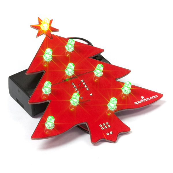
Decorate for the holidays in SparkFun style with the Through-Hole Christmas Kit! This ornamental kit comes with a neatly-cut, tree-shaped PCB, adorned with super-bright green LEDs, and topped with a yellow LED. The LEDs are controlled by a pre-programmed ATtiny85 AVR, and the circuit is powered via a couple AA batteries. The included battery holder has an ON/OFF switch so you can turn the ornament off to save on battery life.
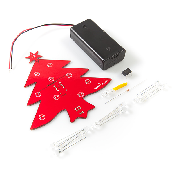
This kit comes as a bag of parts, which you'll need to solder onto the tree PCB. All components are through-hole, so this is a great kit for that first-time solderer. Make sure you install everything with the correct polarity!
Happy holidays, from SparkFun!
- 1x Christmas Tree PCB
- 1x ATtiny85 - Programmed for X-mas Kit
- 1x LED - Basic Yellow
- 9x LED - Super Bright Green
- 1x Resistor 10KΩ
- 1x 2xAA Battery Holder with Cover and Switch
It's a Through-Hole Christmas, Charlie Brown! Product Help and Resources
Core Skill: Soldering
This skill defines how difficult the soldering is on a particular product. It might be a couple simple solder joints, or require special reflow tools.
Skill Level: Rookie - The number of pins increases, and you will have to determine polarity of components and some of the components might be a bit trickier or close together. You might need solder wick or flux.
See all skill levels
Core Skill: Electrical Prototyping
If it requires power, you need to know how much, what all the pins do, and how to hook it up. You may need to reference datasheets, schematics, and know the ins and outs of electronics.
Skill Level: Rookie - You may be required to know a bit more about the component, such as orientation, or how to hook it up, in addition to power requirements. You will need to understand polarized components.
See all skill levels
Comments
Looking for answers to technical questions?
We welcome your comments and suggestions below. However, if you are looking for solutions to technical questions please see our Technical Assistance page.
Customer Reviews
No reviews yet.
With reference to this item: Adafruit receives a letter from lawyers representing Velleman
http://www.adafruit.com/blog/2009/12/17/happy-holidays-adafruit-receives-a-letter-from-lawyers-representing-velleman/
Please? A few more?
There is a bug in the source code posted above. The line for(int s_led=2; s_led s_led < 4; s_led++) should read for(int s_led=2; s_led < 5; s_led++) or one set of LEDs will never light!
I believe the line of code should be
because LED=s_led and the switch statement has cases for LED equal to 1, 2 and 3.
My nine-year old put this together in about 20 minutes - the first time he has fired the solder gun in anger!
Plugged in the batteries and everything worked. He was delighted. ;-)
Howdy - I built the kit last night, but it seems the pattern runs incorrectly.
When I power it on, the yellow LED turns on solid and then it fades in and out sets the three sets of 3 LEDs (lasting about 2 secs for each group).
However, then all the LEDs turn off for about 30 seconds (a seemingly long time).
I'm guessing this is not the correct operation. One thought was that the internal clock is running slow for some reason but not sure how to verify and correct that.
Anyone else have this problem?
Thanks,
Drew
Mine does that as well. I upped the voltage to 5 volts and it runs constantly. It seems two AA cells is just not enough.
They all do that to conserve power.
If it ran continuously, it would get boring after a while.
Wow that yellow LED is so extremely bright!
Can you guys post the software so that we can hack this thing?
Just out of curiosity, what tricks did you use so you don't need current limiting resistors?
Looks like for the Green LEDs, they are forward voltage of 3.0 to 3.4V, so I assume for those, you don't bother with one as 2 batteries shouldn't exceed 3.4V.
For the LED, that has a lower forward voltage. Are you running some kind of square wave with a duty cycle so that you don't overload the LED?
Thanks :-)
The LEDs are controlled using a method called Pulse Width Modulation (PWM). Essentially a square wave whose duty cycle changes in order to create different brightnesses; current consumption can also be managed using PWM.
We also benefit from the fact that there are 3 LEDs on each output pin (except the star). Each pin can only source around 40 mA, so when that current is split between all 3 LEDs we're looking good!
@zv470: Many AVR micros (maybe all? I don't know) have a built-in clock. For example, the ATmega168 defaults internally to 1MHz, but can go up to 8MHz, and only needs an external crystal for MHz > 8MHz <= 20Mhz speeds.
@promethean Thanks :) that was really informative. I ordered an AVR chip and oscillator... so I'm looking forward to lots of AVR fun. Interesting I don't need the oscillator unless I need the faster speed. Wonder if the power usage is a lot less at 1MHz compared to 16MHz.
excuse my ignorance, don't you need an oscillator or something to provide a clock/timer signal to a micro-controller?
I'm pretty sure it uses the internal oscillator.
lol, i didn't read the other comments :D nevermind...
If you plan on routing this board on a CNC mill, an outline with a little smoother shape will help minimize damage to the machine. The outline EAGLE creates is made up by a ton of tiny segments with a lot of sharp angle -- bad stuff from a manufacturing point of view. I generated a new outline that minimizes vector error (direction change, basically) which can be had at this direct link:
http://www.circuitpeople.com/Blog/Tree1.oln
Enjoy!
Can you post the source code for the ATtiny? :)
If you have the actual kit, you should be able to read out the program by issuing a read command to the programmer.
The code should be very simple, but without having a kit it would be hard for me to recreate (though I could get something to flash).
There is also the issue of "the fuses" - they control how some of the ports operate, e.g. if you need a crystal or something else.
(I got an AVR Dragon from digikey which lets me use something called High Voltage Serial Programming that lets me fix wrong fuse settings or other problems, and a chip-clip so I don't need the 6 pin ISP connector - I do use a ZIF socket I got from sparkfun).