- Home
- Product Categories
- GPS
- 20 Channel LS20126 GPS Receiver

20 Channel LS20126 GPS Receiver
Replacement: None. We are, unfortunately, no longer carrying this GPS receiver in our catalog. This page is for reference only.
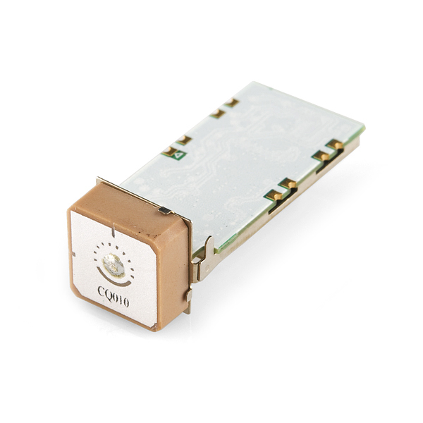
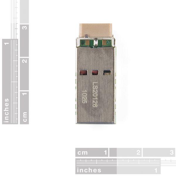
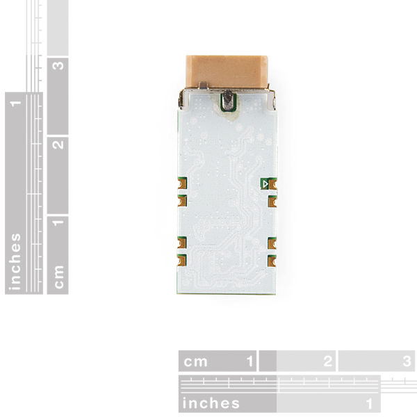
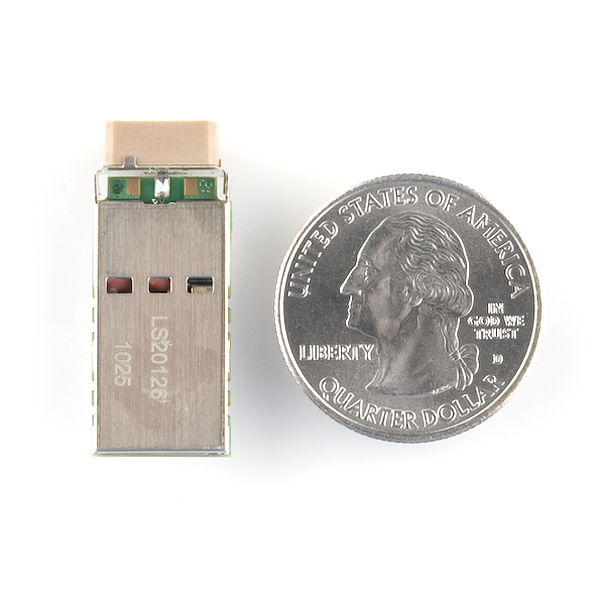
The LOCOSYS LS20126 GPS smart antenna module is a high sensitivity, low power, SMD type, 20 channels with built-in magnetic sensor, 3-axial acceleration sensor L1 GPS receiver and 10mm patch antenna designed for portable applications. The LS20126 is designed for easy and quick integration into customer applications, especially for slow speed or pedestrian mode. This module is pin to pin compatible to LOCOSYS LS200x6 series GPS module.
Breakout board available! Check the related items.
Not sure which GPS module is right for you? Check out our GPS buying guide!
- GPS + magnetic sensor + 3-axial acceleration sensor
- Easy to install (SMT process capable)
- SiRF Star III high sensitivity solution
- Support 20-channel GPS
- Fast TTFF at low signal level
- Capable of SBAS (WAAS, ENGOS, MSAS)
- Pin-to-pin compatible with LS20026 (SiRF solution), LS20036 (MediaTek solution), LS20056(Atheros solution) and LS20076 (ublox solution)
- Provides compass heading over a wide variety of conditions
- 0.5ppm TCXO for optimal performance
Comments
Looking for answers to technical questions?
We welcome your comments and suggestions below. However, if you are looking for solutions to technical questions please see our Technical Assistance page.
Customer Reviews
No reviews yet.
ROTFL : "We are working on a breakout board and should have it shortly after you actually need it."
^^^hahahahahahaha
Awesome! It's like a Linx RXM-GPS-SR-B, but with Compass and accelerometer. Same footprint too, it looks like.
32mA typical at 3.3V and a max of 83mA.. Oh, and a good input voltage range.
Nice find!
any one have any idea how to convert the "RS-232" output from the LS20126 to TTL levels? hooking the TX pin up to the the RX pin on the Arduino results in no data. EN is held high, VCC is 3.3VDC. and of course GND is grounded.
the output is already at TTL levels. your problem might be with the baud rate.
Hi guys,
I am totally new to GPS interfacing and I have read your comments with great interest. My question is the following: Could someone please show me how to communicate with this module (LS20126 mounted on a breakout board) using a PICAXE 18M2 microcontroller? I have tried everything but I am not sure I'm sending the setup messages correctly. When I try to read the GPS module's output via the "serin" command I get nothing. I'm only trying to read a few bytes and then display them on an LCD just to verify that I can extract data.
Thing you should know: All the 18M2's inputs and outputs are TTL (no Schmitt triggers here) Power to the module is 5V regulated The "enable" pin is tied to the above PS The LCD is working perfectly The microcontroller is working perfectly
This is the code that I am using:
serin C.5, T9600_8,("$GPGGA,"),B8,B9,B10,B11,B12,B13 ;read some GPS data pause 100
serout C.6,N2400_8, (B8,B9,B10,B11,B12,B13) ; display values
These are the setup messages I'm sending:
pause 10000 ;wait for GPS to boot serout C.1,T9600_8,("$PSRF100,1,9600,8,1,00C",13,10) ; set communications to 9600, 8, 1, no parity pause 100 serout C.1,T9600_8,("$PSRF103,00,00,01,0125",13,10) ;tell GPS to send GGA msgs once per second
pause 1500
Sorry for the long post but this is driving me nuts! I've been working on this for 12 hours straight with no solution in sight.
I had problems issuing commands to the unit using tera term. I figured out the problem was that the carrage return and line feed were not being transmitted. To fix this go to setup-> terminal and change Transmit: pull-down to CR+LF. I also turned on the local echo to see what was being sent. I also found it easier to copy the entire command you want to send onto your clipboard through notepad or something. Then right-click in the tera term window to paste it all at once in between the output strings and hit enter real quick. Also make sure the checksum value is correct. A quick calculator is found at http://nmeachecksum.eqth.net/ Hope this helps. Also helpful to determine the orientation of the chip is the GPSFox software downloadable from the locosys support website. Oh, yeah and to change the accelerometer output rate to 5Hz use $PLSC,248,1,2*1D.
I would like to ask about a trouble we are having with this device. Precisely in the PLSR Compass. Acording to the datasheet it is possible to reset the coil with the following parameter ( $PLSC,247,00D) or modify the mounting mode with (e.g.)$PLSC,249,1,41A. But so far we aren't able to acomplish any of this modifications. Is it necesary to follow any previous step? We've read that is necesary to enter in a debug mode.... that's right?? How can I do this? Thanks in advance.
Can anyone confirm the orientation this is meant to be used in? One would think that the chip antenna faces upwards, but the datasheet shows that with the M0 firmware, it should be used facing 'forwards' - or is the firmware just regarding which label is assigned to which axis?
Does anyone know if this unit is compatible with an arduino?
Hi,
I'm just a newbie here, please excuse me if my questions are beyond dumb.
I want to use a sensor on a very light mobile robot (low payload capacity) so in terms of weight this seems to be a good fit.
I am confused about the following:
1) The description says "This module is pin to pin compatible to LOCOSYS LS200x6 series GPS module"......so is this module ready to use? or does one need to have another GPS receiver sensor to get this to work.
2) With a normal GPS, when you are stationary, you cannot get the heading or even at startup, the GPS cannot tell which direction the robot is pointing. I assume the magnetometer in the sensor will take care of this by giving heading output? (the specs seem to suggest that but I just wanted to be sure I have understood it right)
Thanks in advance.
1) Pin to pin compatible means that if you had a PCB design for that LOCOSYS LS200x6 module, you could drop in this LS20126 module instead.
This is ready to use. You may be interested in the BOB-10141 breakout board, though.
2) This one also has a magnetic sensor, ie magnetic compass.
Bought this, wired up to the pads and got it working without trouble. I took it out to an open field at night and did a 20-minute static data collect (not moving it). The mag looked pretty good, I'd say +/- 2 degrees noise and no drift, but the GPS was terrible - over ten minutes my position drifted 30m in one direction then over the next ten minutes it drifted 60m back the other way (noise was just a couple meters though). I don't have any other modules to compare with, so it could have been atmospheric effects for all I know, but I would love to hear what kind of long-term stability people see with the other modules.
The accel is a pretty neat feature, but kinda useless at 1 Hz. The data sheet makes it sound like 5 Hz output is possible - anyone know how to do this?
Did you actually get the acceleration feature to work (i.e. the string headed by "$PLSR,245,1" ? I was getting strings back such as this :-
$PLSR,245,1,52,7,217,3,-12,235,31,0,1*1D
Even after pestering Locosys (they wanted to know Company details and production runs....) I managed to get the device Auto-calibrated giving a '7' as the second parameter (before it was 0, un-calibrated). But study the X,Y,and Z Acceleration fields. X is 3, Y -is -12, but Z is 235.
With the unit at rest this is just strange.
I've also noticed that this is more of a tilt unit. Hold the unit at a steady angle and these X and Y values remain at high values.
Locosys now refuse to talk to me because I'm not a major player......soooo, has anyone else managed to solve this riddle ?
Also, can anyone tell me how to decode the "$PLSR,245,2" returns ?
I think this datasheet is quite severely flawed (probably through bad translation), although the Rep. said she was trying to protect their intellectual property rights. If a unit doesn't do what it's meant to do, I think a company has the obligation to everyone to help badly written documents.
Yes, I got the acceleration feature to work. The only time you will see zero acceleration is when the unit is in free-fall (or in space). Otherwise, it shows the acceleration due to gravity (1g = 255). This lets you use the accelerometer as a tilt sensor, but if you know orientation you can subtract out gravity to get just local acceleration.
I believe that "$PLSR,245,2" returns a 3x3 rotation matrix representing the attitude of the unit, of the following form:
att = [ [Xx Yx Zx]; [Xy Yy Zy]; [Xz Yz Zz] ]
If you treat this matrix as a composition of simultaneous yaw, pitch and roll rotations about the inertial frame, you can back-calculate the angles. When I did this, I found that yaw was unspecified (which makes sense), pitch gave a good value but only when there was no roll, and roll gave a somewhat nonsensical value. Perhaps I am just not understanding how they formed the attitude matrix.
How did you get it to auto-calibrate?
Not starting an argument here, but acceleration is measured in meters per second per second. Hence, you have to be moving to be accelerating. Gravity I don't think can come into it.
If I take my board and take the normally front facing LS20126 and face it downwards, I get a zero reading on the Z axis. I suppose I can just factor that out when using the board.
Ummm...I've sworn on my dead brothers grave I'd not tell how Auto-calibration works (isn't that the MOST stupidest thing ever), but if you feel comfortable with posting an email address you don't use too often maybe I'll let slip a few secrets.
"Hence, you have to be moving to be accelerating. Gravity I don't think can come into it."
Don't forget that all points on the surface of the Earth are accelerating upwards at about 1g relative to the local intertial frame. If it wasn't for this effect, your Wii Remote wouldn't work right.
I found this online:
http://dlnmh9ip6v2uc.cloudfront.net/datasheets/Sensors/GPS/core%20module%20calibration%20procedures%20.pdf
But there isn't enough help there to get the auto-calibration to work. Please help.
derekturkelton@gmail.com
We recently updated the datasheet which now includes the calibration pages, have you checked there? If you're still having trouble, drop us an email in tech support and we can help you out.
don't think ???
Hit me up at reiterandrew@hotmail.com and we'll go from there
I've had read your comments...Could you solve it?? How??? Please some help will be great. ram00alonso@gmail.com
I would like to ask about a trouble we are having with this device. Precisely in the PLSR Compass. Acording to the datasheet it is possible to reset the coil with the following parameter ( $PLSC,247,00D) or modify the mounting mode with (e.g.)$PLSC,249,1,41A. But so far we aren’t able to acomplish any of this modifications. Is it necesary to follow any previous step? We’ve read that is necesary to enter in a debug mode…. that’s right?? How can I do this? Thanks in advance.
This unit is Great. It is true Three axis, and even does all the vector calculations for you.<br />
<br />
Remember it is an accelerometer, not a gyro, so all of you with grand plans for autonomous flying objects will still need the 9DOF board :)<br />
<br />
The antenna must be to the front for the compas to work, so that is a bit of a compromise.<br />
<br />
really good unit.
Actually if you have a good precision magnetometer I think you can get by without the gyro. Obviously this is not the case here because you can only get 5 magnetometer readings per sec, but I'm thinking that with the addition of a single 3-axis gyro you get everything you need for an intelligent quadcopter autopilot.
I was just about to order a bunch of sensors + a GPS for my future autopilot, but I started browsing the available GPSes and found this one and I'm now seriously thinking about using just this GPS + a gyro. If I'm not mistaken, it looks from the datasheet like you can reset the GPS's internal position/orientation keeping to some value, doesn't really matter what value, and it will try to keep track of your movement even without a GPS signal? Basically a 6DOF ready to use AHRS. I guess I need to try it. I'm also thinking that the 5Hz magnetometer readings can be used to correct the gyro values to make it basically drift-proof.
Has anyone been able to solder wires to the pads and make it work?
Looks like 1Hz from the datasheet
Someone knows if this GPS works with Arduino? I want to use the TinyGPS library, will I have problems with it?. Any advice to avoid SMT process? (Compatible breakout boards, is the space on the connectors enough to solder some wires(Like the LS20031)?
Wondering if anyone ever got this working with arduino Im currently looking into doing that but would like to make sure its possible, before spending money
For technical questions, please contact techsupport@sparkfun.com. Thanks.
"We are working on a breakout board and should have it shortly after you actually need it."
I am starting to design a system which will combine this LOCOSYS module with ZeeBee and Arduino.
Any update on the breakout board?
Would there be any interest (by anyone) in combining efforts in coming up with a general purpose design?
At the very least, it would be helpful to have someone review my Eagle files before I use them to produce some PCBs.
Thanks
Our breakout board is in the works, but no ETA. For joining forces, contact techsupport@sparkfun.com. As for design review, we do not provide design assistance, you will have to find someone who can assist you with that, sorry!
Anyone have this working? After reading the datasheet I am still confused as to how to orient the thing. Which way is north? I am getting accurate readings for basic RMC stuff, but heading reading bops around when at a standstill. I know the mag compass is supposed to give COG when not moving, but the reading does not hold steady. Also, what directions are the XYZ axis for the g sensor? The datasheet shows the board laying flat, with ant pointing forward.
Any input is appreciated.
Thanks.
-Larry
So, which way do you orient this thing? What do you point toward the sky?
Just like all ceramic antennas for GPS, it needs to be oriented to see the sky (facing upwards).
not correct, on this module, the antenna must be facing forward M0 mounting. <br />
it is not ideal for gps reception, but seems to work.<br />
<br />
the compass relies on this mounting position. <br />
The news brief still has the LED.
Looking at the datasheet, the recommended footprint has two slots, plus a notch in the side of the board if you don't want the antenna extending out. Any suggestions for getting Eagle to deal with that? (And for that matter, getting a fab house to make it) I suppose two pads with big holes would work.
Don't be intimidated by the mechanical aspects of this part. It's a great little device, and if you're comfortable with the soldering cutting the notch and slots is fairly straightforward.
The notch took a few seconds to cut using a Dremel with a cut-off wheel. For the slots I drilled the hole at one edge of the slot, and then used a broken blade from a jeweler's saw to extend it. I was making my own board (and thus had a lot of steps like this), but it your fab house won't do this there's no reason you couldn't add the notch and slots to a board this way after you got the board from them. The larger hole you suggest should also work.
For the design, I just drew the notch on the silkscreen layer of the footprint and then watched to make sure that there weren't any tracks or zone fills beneath it when I laid out the board. For the slots, I was surprised to find that KiCad has an option for oval drill holes. If your fab house supports these than they're worth looking for in Eagle; otherwise you could just use a large hole or mark the drill hole at one edge the slot.
I make slots in my boards by stacking drill hits. I've had good luck with BatchPCB using this technique.
It's all fixed now, sorry about that. Just a glitch in picture uploading.
I think someone uploaded wrong photos, unless this GPS looks like a LED bar graph.
I'd have to imagine Taiwan would be none too keen on exporting dual use technology, given the periodic saber-rattling and missile tests going back and forth over the Taiwan Strait.
The datasheet isn't very clear about this, but I suspect that the magnetometer is 2-axis only.. and there doesn't seem to be any way to get it to report raw measurements, just direction and magnitude. Shame, with just that one extra axis it would be able to pin down location and orientation on all six DOF- latitude, longitude, elevation, yaw, pitch, and roll. This also means the compass becomes useless if it goes too far off level.
I've read that sensor manufacturers purposefully avoid combining high-quality 3-axis sensors like this, or else charge a big markup because then they have to deal with ITAR compliance- can anybody confirm what truth there is to that?
It's a Taiwanese company I don't think they would have to be compliant with ITAR...
This GPS has my brain rocking with ideas. One question so far though. Is it safe to assume the modules sold will be loaded with the M0 firmware? Per section 8.4.4 in the datasheet, different firmwares are needed depending on the orientation that the module will be used on the PCB. M0 will probably be most common, but a particular case I already use would work best with M4. However, since it states to contact Locosys before ordering for the module, my guess is the firmware can't be changed by the customer.
The one I have from Sparkfun is mounting mode M0, as reported by the PLSR Compass Measurement Report 1 sent by the device.