
RedBoard Kit Quickstart Guide
Overview:
The RedBoard Kit functions as both a learning tool and as a fully-functional development board. Whether you're a soldering/Arduino beginner, looking for a learning tool, or an advanced user just looking for a fully-customizable Arduino -- the RedBoard Kit is a perfect addition to your electronics arsenal.
![]()
This guide will touch on everything you need to get your RedBoard Kit up and running. We'll cover both assembly and basic usage, specifically how to program the thing. We'll effort to get your RedBoard Kit up and running as quickly and as pain-free as possible.
Requirements:
First and foremost, you'll need the RedBoard Kit and everything that comes with it:
- 1x RedBoard Kit PCB
- 1x ATmega328 with Arduino Uno bootloader
-
1x 5mm red LED
-
1x 1N4001 diode
-
1x MCP1700 3.3V regulator
-
1x PTC
![]()
Missing any parts? (Bad SparkFun kitters!) Drop our customer service team an email. We'll get them out to you as soon as possible.
At a minimum, the required tools for assembly are a couple opposable digits, a really basic soldering iron, a bit of solder and some cutters. In addition to those tools, other items you might find helpful include needle nose pliers, and perhaps a third hand, or vise, to keep everything nice and stable.

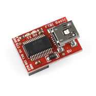
Finally, you'll need something to program your kit. To program the board, you'll need something that converts computer talk (USB) to Arduino talk (serial). For this, I recommend our FTDI Basic Breakout, or an FTDI Cable.
Conveniently, those programmers can also be used to power the board. However, if you want something with a little more juice, you could use a power supply with a barrel jack connector. Something that supplies at least 6V, but less than about 15V. Our 9V wall adapter is a good choice.
What it does:
An Arduino is a rock-solid, open-source, electronics prototyping platform. It's centered around an ATmega328 microprocessor, an 8-bit processor running at 16MHz. More important than the specs though is that the Arduino is supported by a huge community, an easy-to-use development environment and a well-documented programming language.
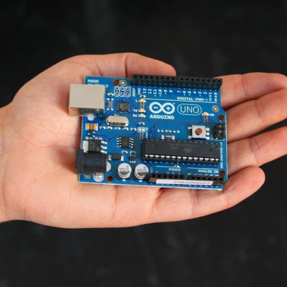
The "standard" Arduino is the Arduino Uno, and since it's open-source, there are all sorts of variations on the original. The RedBoard KIT is one of those variations. It has the same microcontroller as the Arduino Uno, as well as the same bootloader on it. It's also the same size and footprint, so it's compatible with most of the popular Arduino shields.

What doesn't the RedBoard Kit have? Well, it doesn't have a USB-to-serial converter on it. That's what's used to program the Arduino, and is usually either an ATmega8U2 or an FTDI FT232RL. The problem is both of those chips are tiny and require much more advanced surface-mount soldering. To keep the soldering at a beginner level, we opted to leave those chips off. Instead, you'll need an FTDI cable to program the Arduino. More on that later. Let's do some soldering!
How to use it:
Usage of the RedBoard Kit can be broken down into two parts. First, you've obviously got to assemble the thing. That's half the fun! Once assembled you can program it and use it just as you would any Arduino.
Assembly
Assembly of the RedBoard Kit requires soldering. Soldering all the parts to the PCB will form a nice, solid, electrical connection. If you've never soldered before, don't fret! This is one of our easier soldering projects. Every part is through-hole and well-spaced. But, if this is your first time, I'd encourage you to take a quick detour over to one of our excellent soldering tutorials.
With the kit you should have received a pamphlet with some very stylish soldering instructions (thanks SparkFun artsy-fartsy department!). Out of both laziness, and admission that my MSPAINT skills don't come close to that of our graphic designers, I'm just going to regurgitate those instructions. Follow these step-by-step instructions, and you should be golden. Click any picture below to make it larger.


You'll probably notice the common trend on each of those steps is:
- Insert the part into the top side of the board.
- If the part is polarized (more on this later), double check to make sure it's inserted in the proper orientation.
- Solder ALL legs of the part to the bottom of the board.
- Clip off any excess leg remaining.
And that's that. Onto actually using the kit...
Hardware
As mentioned above, the RedBoard Kit lacks any USB-to-Serial circuitry, like an ATmega8U2 or an FT232RL. This is what allows your computer to communicate with the Arduino, and it's required to program the microcontroller. In lieu of that circuit you'll need one of our 5V FTDI Basic Breakouts (and a USB cable), or a 5V FTDI Cable.
The first time you plug a FTDI Basic Breakout into your computer, you'll need to install some drivers. This is as good a time as any to download the most recent version of the Arduino IDE, if you haven't already. Make sure you get the version that matches your operating system; they should have everything (Mac, Linux, Windows) covered. Unzip the folder into some place convenient on your computer.
Instructions for driver installation are already pretty well laid out by both Arduino (Mac, Windows, Linux) and FTDI. I'll leave that to the pros.
With the FTDI drivers installed, you should be able to safely connect it to your RedBoard Kit. Line up the BLK and GRN labels. Don't freak out when RX-I and TX-O don't line up, it's almost always normal to see these crossed. If everything's gone right up to this point, the power LED of the RedBoard should illuminate, and the status LED should even do a little blinking.
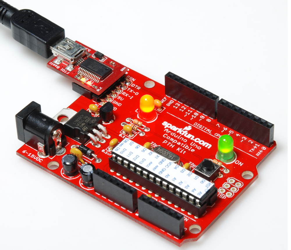
As a bonus, the FTDI Basic board not only programs your Kit, but it also powers it!
Programming
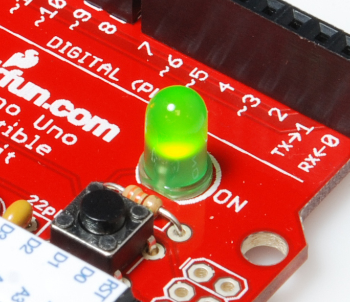
If you're a software person, you're probably familiar with "Hello, world". Well, the hardware version of that is blinking a single LED. The idea is, if you can make an LED blink, not only do you have proof that both the Arduino and its development environment (IDE) are playing nicely, but you've also taken your first step towards learning the Arduino programming language. So, let's load blink!
Open up Arduino.exe, which should be in the first, main folder of the Arduino zip file you downloaded earlier.

This will open up the Arduino IDE, which looks something like this:

To load Blink, go to File > Examples > 1.Basics > Blink. That should load up the sketch above. Less than 10 lines of actual code that make the LED go blink.
There's just a bit more housecleaning before you can upload the sketch. First, make sure the Tools > Board menu is set to Arduino Uno.

Next, select the Serial Port that matches your FTDI board. If you have just one FTDI board plugged in, this is usually the only other option that's not COM1 (COM1 is often reserved for an actual serial port). If you're having trouble finding your FTDI's COM port, try unplugging it, checking the Serial Port list, plugging the FTDI board back in and scanning the Serial Port list for any inconsistencies.

With everything set, go to the toolbar and click Upload.

And with that, you should be greeted with that always comforting, palpitating LED.
Resources:
I'd encourage both the newbies and the vets to familiarize themselves with the Arduino website. There you can peruse their tutorials, and you can learn a thing or two from the excellent Arduino community on the forums. Other great Arduino resources include:
- Arduino's Langauge Reference Page - An exhaustive list of all functions, variables, constants, etc. in the Arduino Programming language.
- Arduino's Examples Page - Great explanations of some of Arduino's common example sketches.
- Arduino's Libraries Page - A good roundup of the most common Arduino libraries
- Instructables Arduino Channel - Need some project inspiration? Check out some fantastic instructables all driven by an Arduino.
Conclusion:
Congratulations on your fancy, new, fully-functional RedBoard kit! If this is your first foray into the world of Arduino, I hope this tutorial has encouraged you to seek out more and more Arduino projects, examples and tutorials. If you're a seasoned vet, I hope this kit will help feed a very healthy electronics/Arduino addiction. Enjoy your future Arduino endeavors!
If you still have unanswered questions or comments about the tutorial, please leave your thoughts in the comment box below.
And to agree with the gang at Sparkfun, for this long since discontinued Red Board PTH (In retail shells) it does need an honest to Entropy FTDI Basic to work properly/ The FTDI Friend that Adafriuit created for something else entirely just does not work here. So we can ignore my remark.
Well the board works when powered via the barrel power connector. However connecting it to a FTDI friend that was bought for a completely different project and instructing the Arduino software to believe its talking to a Uno produces this error: Binary sketch size: 1,084 bytes (of a 32,256 byte maximum) avrdude: stk500_getsync(): not in sync: resp=0x00
Now what? Is it possible something is not quite right? I followed the instructions to the letter.
Somebody switched the two 5mm LEDs