
Run SPOT Run
Let's jump to the punch line: With a clear, open view of the sky, you can transmit small amounts of data (think text messages or 41 character tweets) across a low-orbit satellite network from nearly any surface of the earth. The SPOT Connect Satellite Messenger is easily controlled with a few serial commands. This opens the door to all sorts of remote data sensing and tracking projects. It's not cheap ($150 for the hardware, $100 a year for the service, $20 for the breakout board, $0.10 per message) and you won't be streaming YouTube, but it's a heck of a lot better coverage than cellular.
Part 1 covers the serial interface requirements. So if you're just looking to use the breakout board, start there.
Part 2 covers the tear down and reverse engineering required in this project. Good for eye candy but may be a bit technical for folks that don't enjoy a good continuity test now and again.
Part 1 - Serial Interface
If you've got the breakout board and are eager to get started, here's information about the command structure.
You can find example code on the Run SPOT Run github repo. The breakout board layout files are also there.
The SPOT Connect receives serial messages on the RX-I pin and transmits messages on the TX-O pin. All communication is at 115200bps, 8N1. Each message or command begins with a preamble (0xAA), the length of the command, and then the remainder of the packet. There are no termination characters or CRC.

Remember: You need to activate your SPOT (pay your $100 per year) before the SPOT website will start showing the position and messages from your device. You will need to be in an open, clear area outdoors. I've gotten my SPOT to work in a windowsill but assume you will need to be outside. SPOT does not work through roofs.
Send Message:
0xAA 0C 26 01 00 01 00 01 54 65 73 74
0xAA : Preamble
0x0C : Length of command (0x0C = 12 bytes)
0x26 : Transmit message command
0x01 : Message type (0x01 = Ok, 0x04 = help, 0x40 track)
0x00 01 00 01 : Unknown status and command bytes
0x54 65 73 74 : These are ASCII characters 'Test'. There's our message! Change this string and the length command (if your string length is longer or shorter than 4).
Request Status:
0xAA 03 52
0xAA : Preamble
0x03 : Length of 3
0x52 : Request status. The SPOT will then respond with a large packet of 41 bytes. See Status Response Packet below.
Request last known GPS location:
0xAA 03 25
0xAA : Preamble
0x03 : Length of 3
0x25 : Request last known GPS location. Unit will respond with a 12 byte packet containing the encoded Latitude and Longitude. See one of these great articles to learn how to decode the data.
Cancel Message Command:
0xAA 04 51 10
0xAA : Preamble
0x04 : Length of 4
0x51 10 : Cancel last message
Send Help Message:
0xAA 0C 26 04 00 01 00 01 54 65 73 74
0xAA : Preamble
0x0C : Length of 12 (hex, remember?)
0x26 : Transmit message command
0x04 : Message type (0x04 = help)
0x00 01 00 01 : Unknown status and command bytes
0x54 65 73 74: Our message 'Test' in ASCII letters
Status Response Packet:
The SPOT Connect will respond with a 41 byte packet (a monster!). You can get the full OpenOffice .ods spreadsheet here. What!? You don't use OpenOffice? Cool, here's an XLS.
0xAA 2B 52 00 00 01 04 06 01 00 07 ....
0xAA : Preamble (array location zero)
0x2B : Length of 43. But this is completely weird. The length is always 41 bytes. Very odd indeed. (array location one)
Rather than rattling off all the bytes, here are the good ones:
Location 7 : Unit status (0x00 = GPS/Radio powered off, 0x07 = GPS searching, 0x0F = GPS lock, 0x06 = transmitting to satellite network). Note: Once the unit has GPS lock it will power down the GPS receiver and move to radio transmission.
Location 11 / 12 : (ex: 0x1BF = 447s) Seconds until next transmission. During GPS search it is zero. The is a number that is different after each transmission. It will start at an unknown about (such as 447s) and count down to zero where the unit will then re-transmit.
Location 19 : Number of tries sending message. This will increase from 00 to 01 after GPS lock. It will increase again after seconds until next transmission reaches zero. It will increase from 00 to 01 to 02. After the 02nd transmission attempt reaches zero seconds, the unit will shut down the radio front end and go to status 0x00.
Location 26 : GPS lock achieved. This will switch to 0x01 once a GPS lock is achieved. Once this switches to 0x01 it is common for the phone app to request the last known GPS location (so you can too!).
Location 31 : Number of satellites in view. This will increase from 00 to 04 or more (I've seen as high as 08 in testing). However, once the unit obtains GPS lock it will turn GPS off and this number will return to 00 during the attempts to broadcast the location and message to the satellite network.
Part 2 - The Teardown and Reverse Engineering
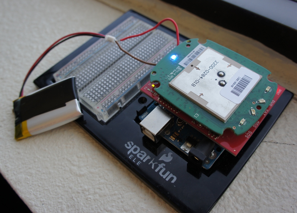
I started this project around Christmas of 2011 after walking past Aaron's office at SparkFun. He had a chunk of electronics hooked up sitting on his window sill. I immediately recognized it as the original SPOT geolocator. After losing my first high altitude balloon to Kansas, I had purchased a SPOT a few months earlier as a backup locator beacon. Aaron mentioned that someone had figured out how to send the right commands to get the SPOT to transmit encoded information (rather than just Lat/Long coordinates).
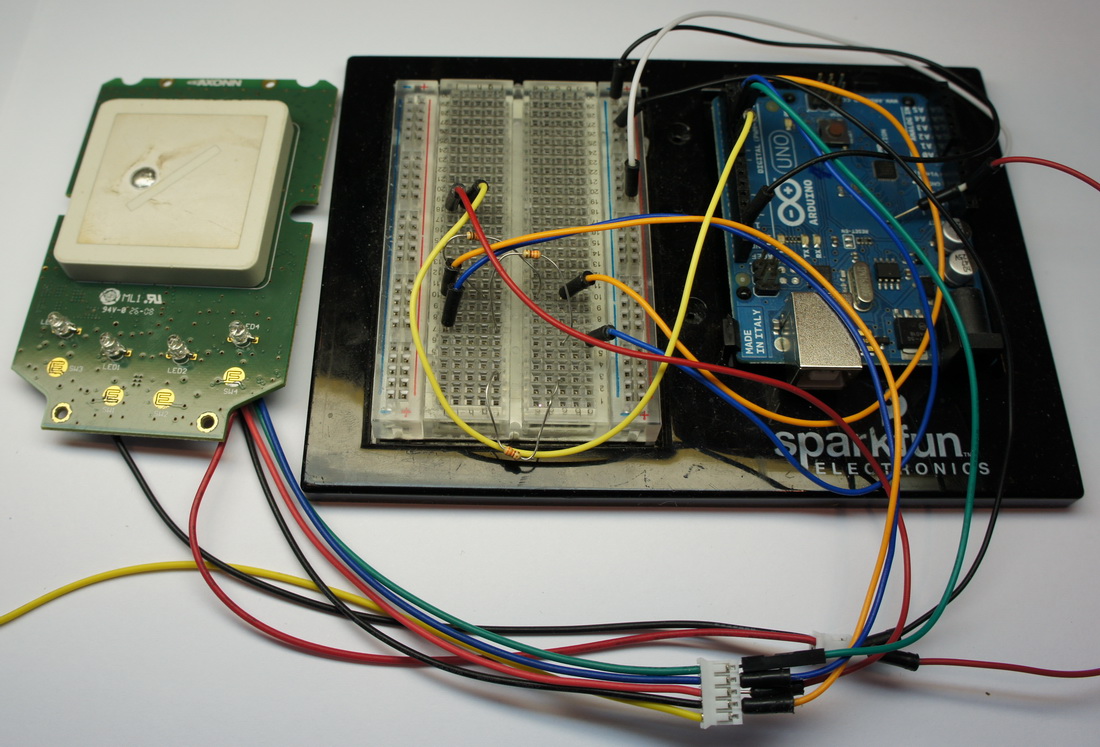
So I set out to replicate Natrium42's work. He did kind of an amazing job of figuring out which byte was responsible for what. I'm still not entirely sure how he figured out byte five of the setup message was the RF channel. Above is my attempt at controlling SPOT (the original, now dubbed 1).
Disassembling the SPOT is easy enough, but you really have to mod the hardware to tap into the serial lines. You can see here that I hot aired off the MSP controller with the Heaterizer (yes, it can do modest SMD rework) and added the various serial connections. 5 seconds after I had removed the MSP I realized I could have left the MSP in place and simply pulled the reset line low on the MSP. Dah! Oh well. After a few hours of serial packet hacking, I found I could send and receive packets reliably to the STX2 satellite radio. After using the SPOT 1 for a few days I found it had pretty bad antenna transmission and the GPS chipset is pretty low-end. The other limitation is that you can really only transmit modified location information, limiting you to 5 bytes of user data. Not horrible, but the recent release of SPOT 2 and SPOT Connect got me interested in hacking other platforms.
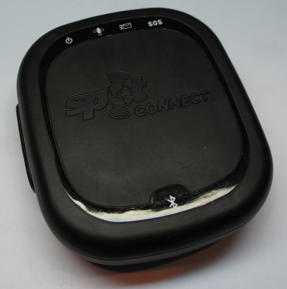
Enter the SPOT Connect. For $150 (there was a $50 rebate which brought it down to $100) you get a black box that connects to your cell phone over Bluetooth. From my Android phone, I could send messages over Bluetooth to the SPOT, and it piped out my message over the sat network to anyone on my contacts list. "Hi Mom!" takes on a whole new meaning from the middle of the Atlantic.
Like many of the projects landing on my desk (Nest thermostat, Laser tape measure, Wiimote) the SPOT didn't hang out for long before screws started to fly.
Hello miniUSB port! Disassembly was easy with just a few simple Phillips head screws to remove.
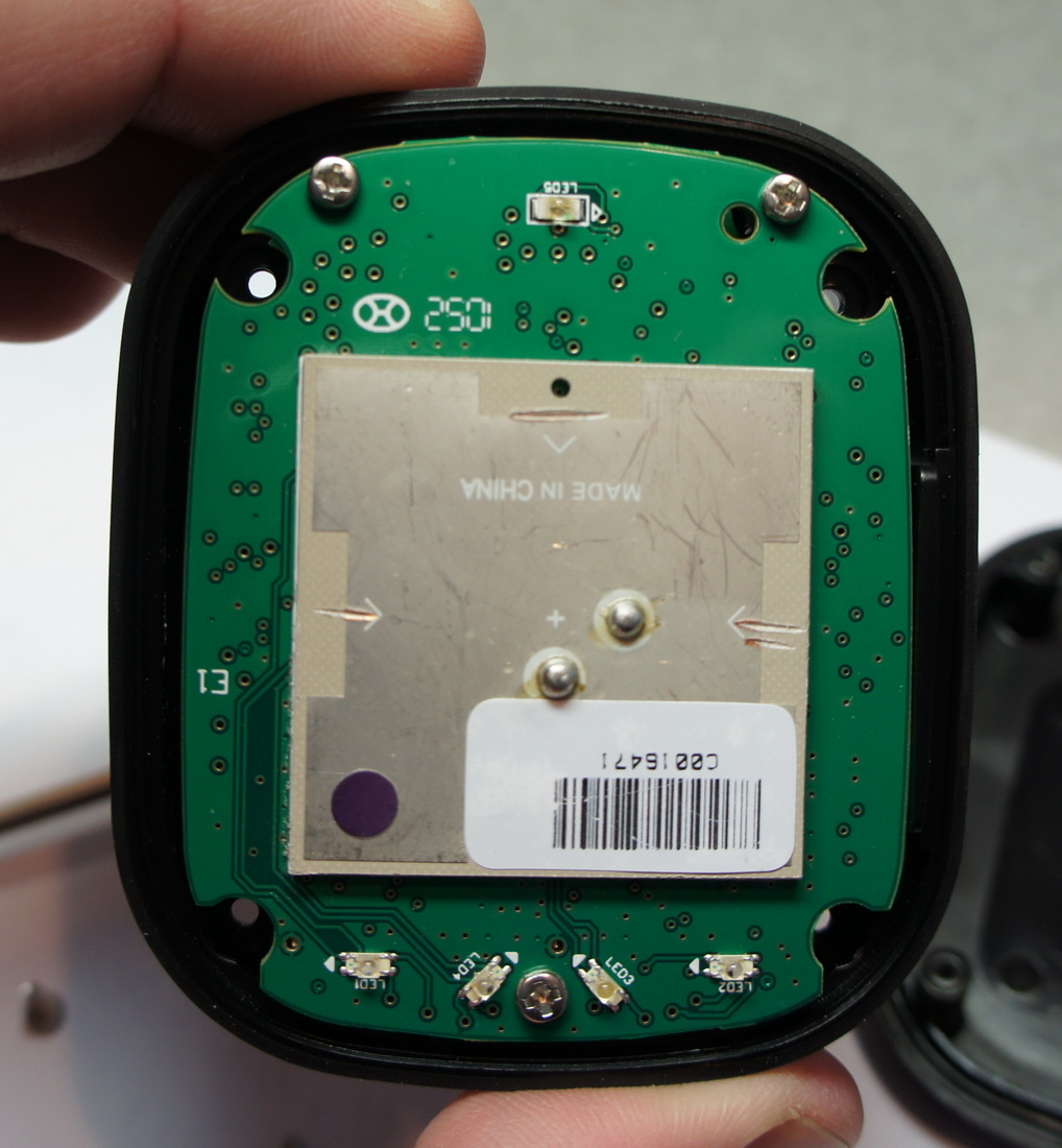
This is the combination satellite transmission antenna and GPS receiving antenna on the front of the main board. The odd slice marks (that look like arrows) are the intentional scratches made during antenna calibration. Antenna tuning is black magic to me. You can also see the 5 LEDs from the top in clock wise fashion: Bluetooth, On/Off, GPS, Satellite, SOS.
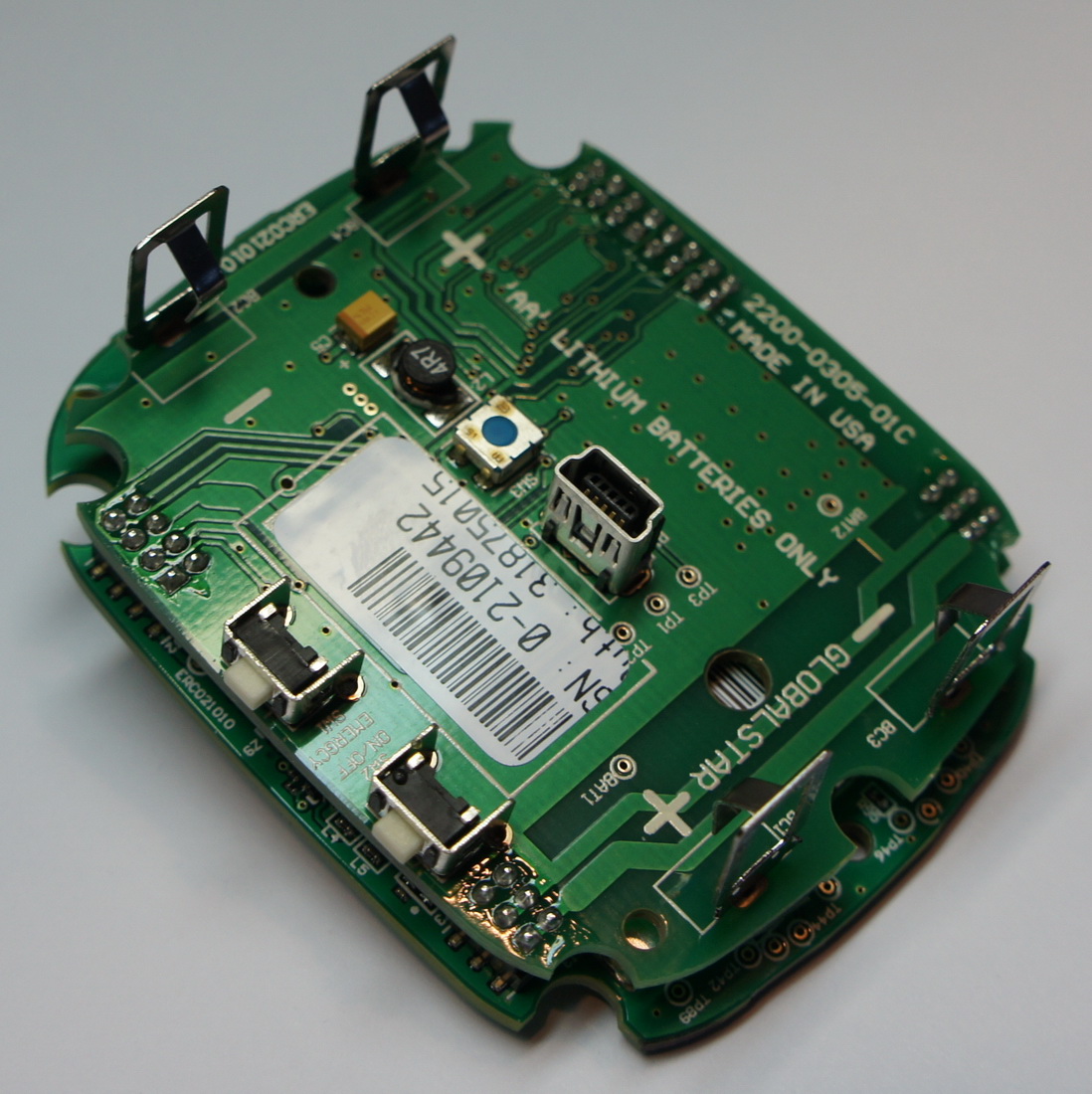
There is a stack of two boards inside the SPOT connect. Here is the daughter board (responsible for power) stacked on top of the main board. This stack up of boards is what originally intrigued me from Travis Goodspeed's write up and pictures. These interconnects make it a lot easier to hack by listen to what's going on between boards. It also opens up the potential for easy end-user hardware modification. Buy a SPOT, unplug one board, plug it onto a SparkFun breakout board and you shouldn't have to solder anything! This was the idea anyway.
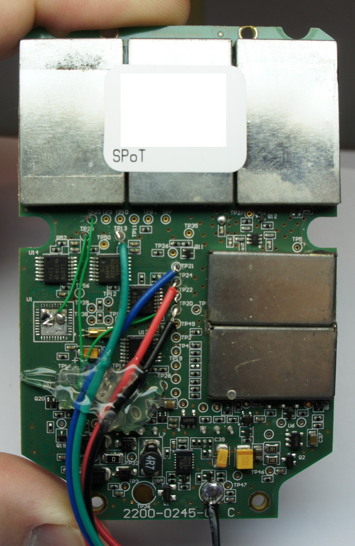
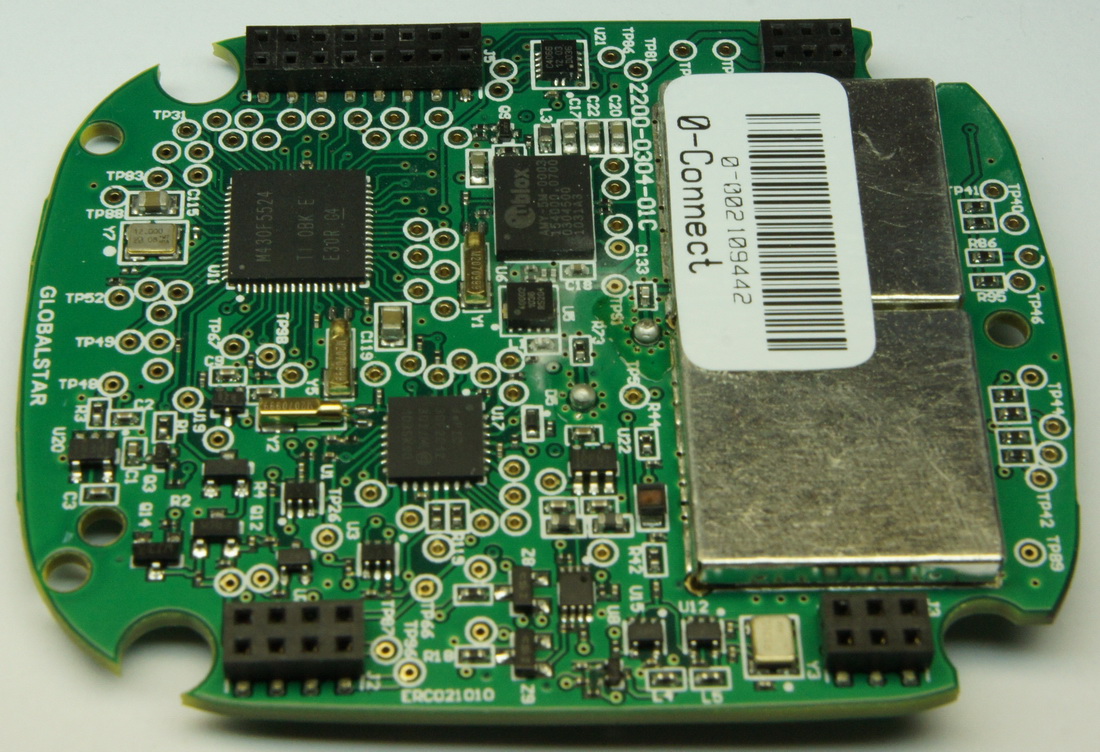
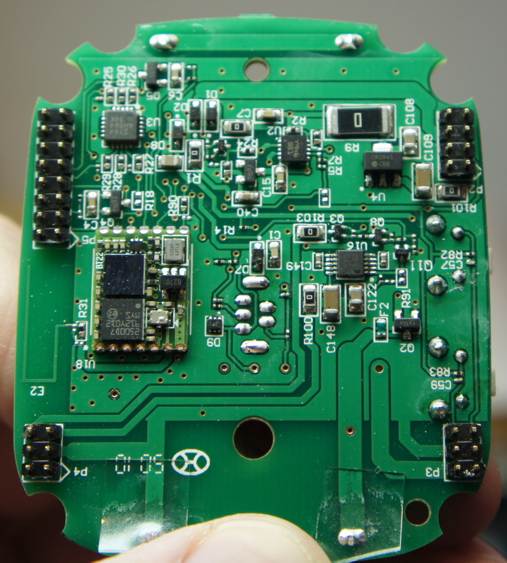
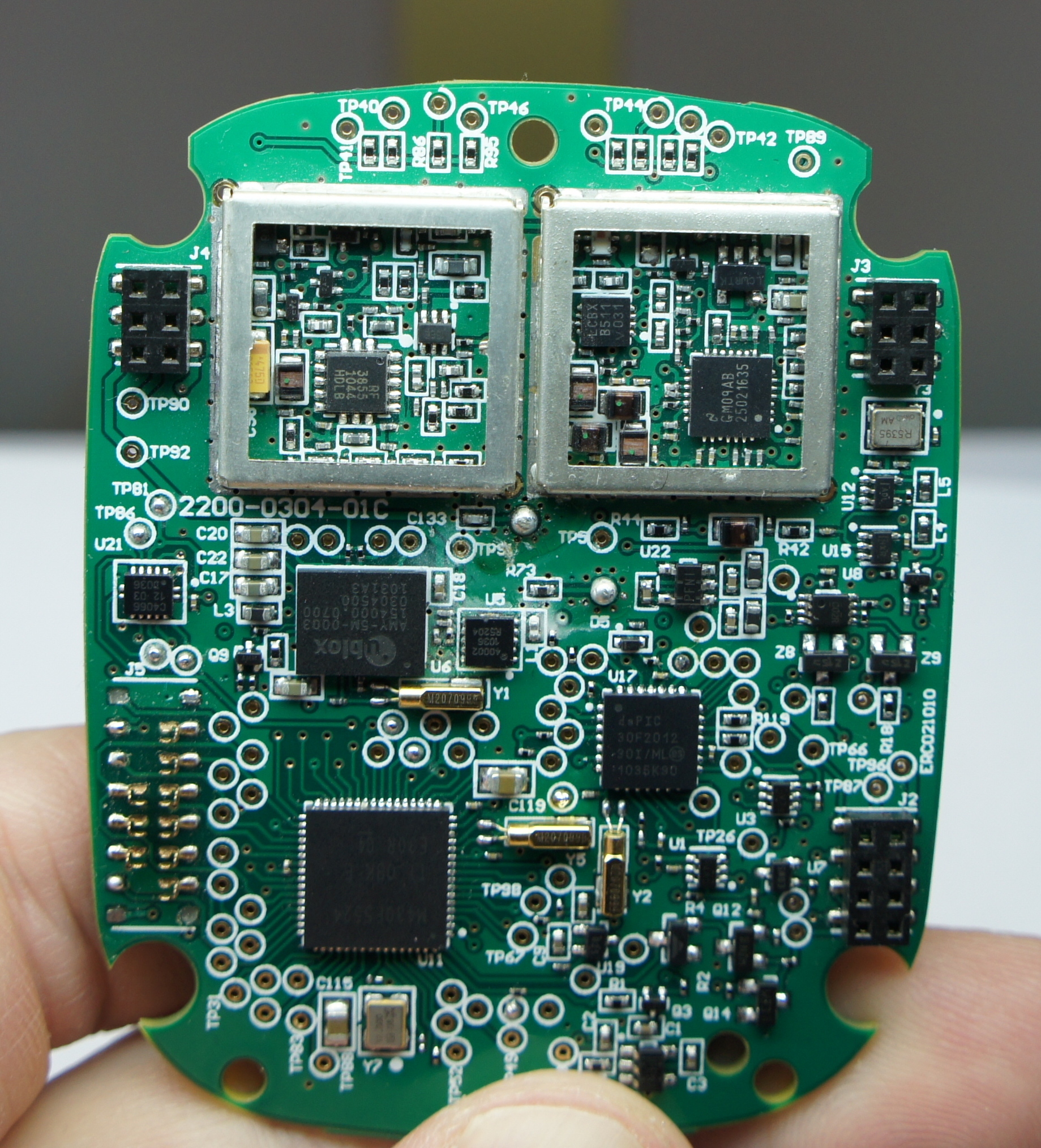
This is the back of the main board.
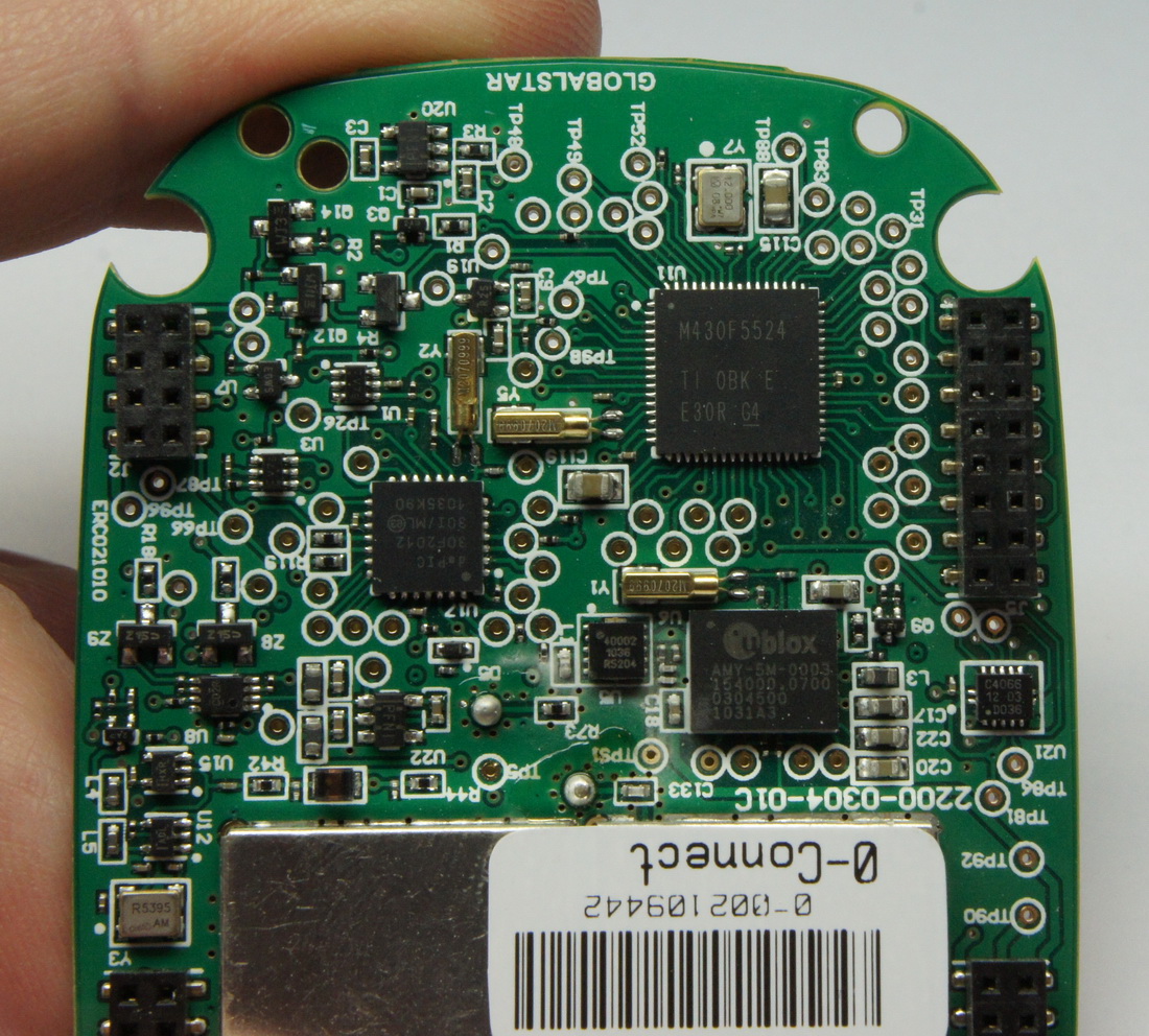
Here's a nice high-res image of the main players. The main brain of the SPOT Connect is the MSP430F5524. It does everything. The satellite radio front end is controlled by a PIC30F2012. The GPS chipset was upgraded from the original SPOT to a respectable uBlox-5. You can also see the proliferation of test points on this board. This was made to be hacked!
Here is the back of the power board. It is much less populated but contains some very interesting surprises.

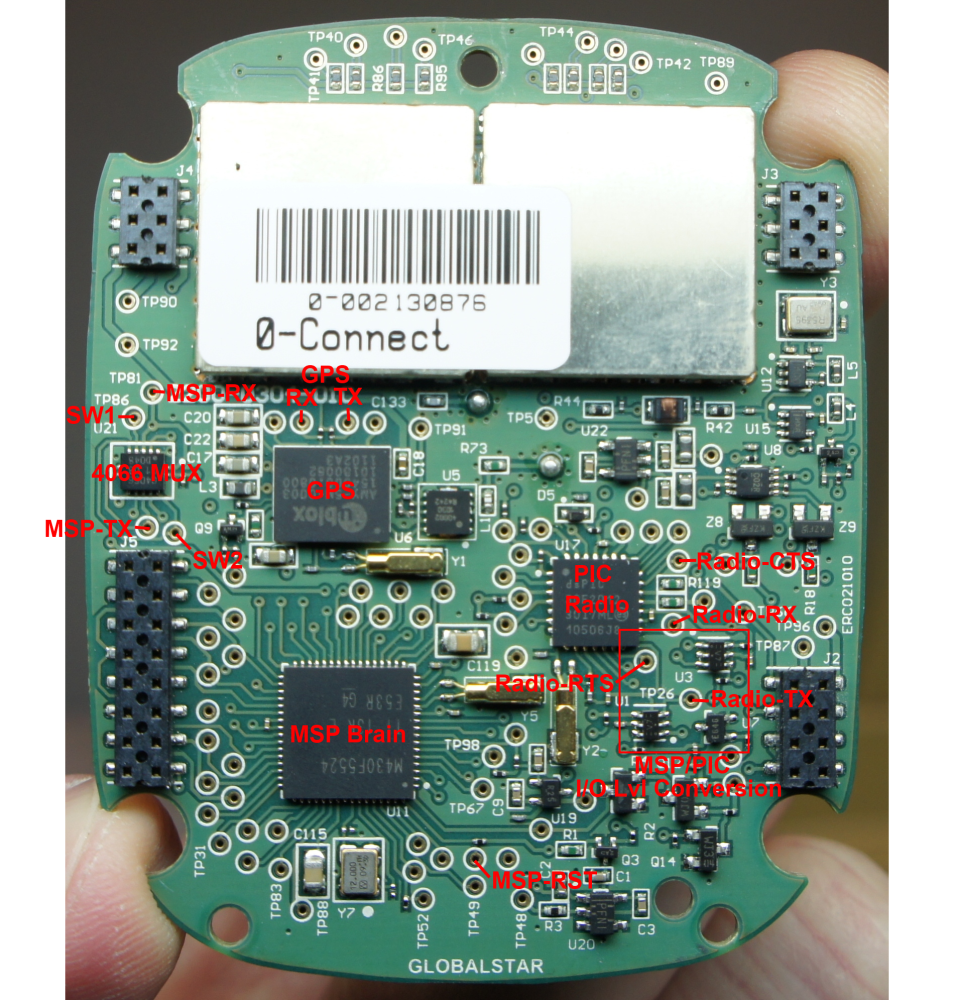
I first set out by continuity testing a lot of the IC interconnections. I originally thought I would do what Narium43 did and take over from the MSP, and talk to the radio/PIC directly. To do this I had to locate the GPS TX/RX pins and the TX/RX pins going to the radio (now the PIC30F2012).
Reverse engineering gets surprisingly easier as you do more of it. I had poked and prodded the SPOT 1 quite a bit which gave me some phenomenal advantages when working on the SPOT Connect. It turns out the MSP is connected to the GPS and radio in the same muxed UART via a quad analog switch (74LVC4066) as it was on the original SPOT 1!

So I broke out the faithful Logic analyzer (this thing is worth its weight in gold and has saved my life many times) and started listening.
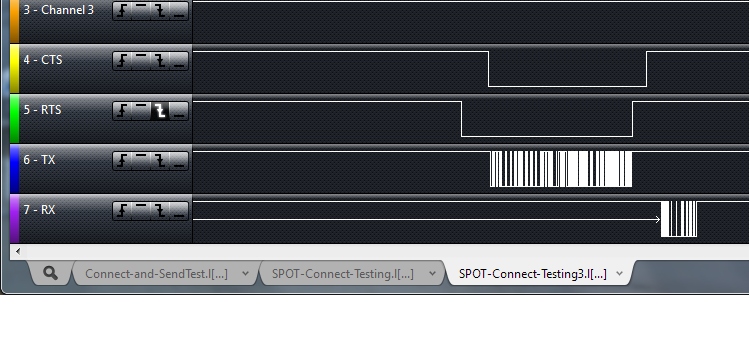
The serial interface between the MSP (brain), PIC (radio), and uBlox (GPS) was similar to the SPOT 1 that Narium had decoded. It had the same preamble, # of bytes, and a CRC byte or two at the end, but the number of bytes was significantly larger. I chalk this up to the more complex radio communication going on to send full character streams instead of just coordinate information. After a few hours of trying to make sense of the 29 byte packets, it suddenly occurred to me (and with the help of Travis' link to the BT module datasheet) that there must be some additional serial coming to/from the Bluetooth module via the smartphone application.

Sure enough - there are TX and RX pins from the Bluetooth module on the daughter power board running to the MSP on the main board at 115200bps! There is some overhead that the cellphone application sends ('hi, how are you?', 'I'm bluetooth ID blarg', 'can I get access?') but it's all junk that we can skip.
If you can get the following characters into the BT-TX pin of the main board, the main board will then transmit the word 'Test' plus your Longitude and Latitude at 115200bps:
0xAA 0C 26 01 00 01 00 01 54 65 73 74
0xAA : Preamble
0x0C: Length of command (0x0C = 12 bytes)
0x26 01 00 01 00 01: All status and command bytes, currently unknown but can remain unchanged
0x54 65 73 74: These are ASCII characters 'Test'. There's our message! Change this string and the length command (if your string length is longer or shorter than 4).
We should now be able to ditch the daughter power board and plug the main board onto a breakout board for our own purposes. I spent a few days tracing all the power pins and checking the noise levels on various buses. There are multiple DC to DC converters on the power board and injecting noise into the GPS or PIC controller will severely degrade GPS reception and cause satellite transmission issues.
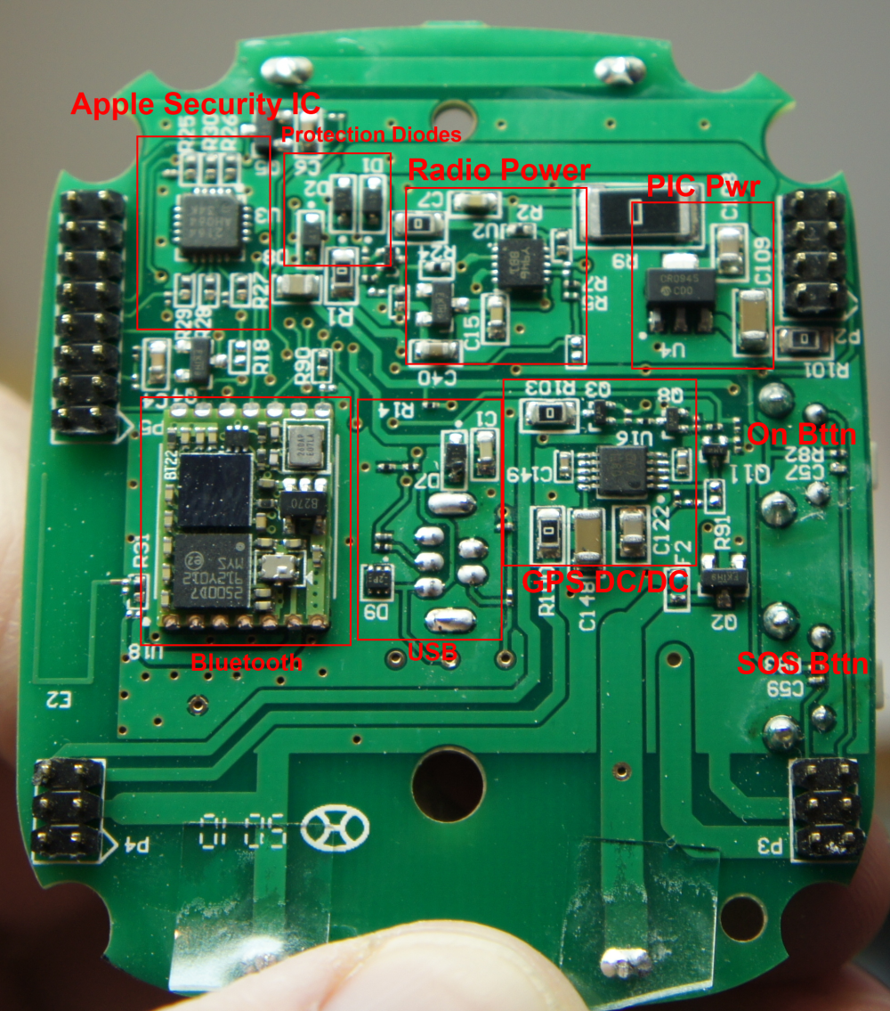
Apple security IC?! What is that? The MFI341S2164 is an authentication co-processor that Apple requires on approved iPhone peripherals. Crazy! Here's a schematic I found showing how a MFI341S2164 is wired up. The 20-pin QFN label 2164 on this board does indeed match the schematic connections. This IC is pinged by the MSP over I2C after the unit turns on. If the MSP doesn't get a response from the IC the unit will got into one of many failure modes (blinking various LEDs in various patterns). Luckily, if we put the unit into Bluetooth discovery mode (holding the On button for more than 5 seconds) the MSP never talks to the 2164 so our breakout board doesn't need to counterfeit a response on the I2C lines (this is a very good thing).
The other IC and power control groups are fairly straight forward, however the PIC power block is worth noting. The various DC/DC converters produced some power rails that were fairly noisy (between 50 and 150mV of ripple). The PIC has a linear regulator and some nice decoupling which produces 3.0V with very low ripple (10-20mV). I found this was required on the breakout board to get good satellite transmission. I assume noise powering the PIC will translate to noisy in the radio transmission.

Going back to the main board, you can see the pins and various functions of the connectors. Most everything was identified.
Here are the major test points identified. You shouldn't need to wire to these points unless you're getting really nitty gritty. If you need a hi-res image of the board without labels you can find it here (good for IC identification).
Here's an image of the inside of the RF shielded areas. I believe the left block contains the receiver for the GPS signal. The right side contains the amplifier for the satellite transmitter.
And just because I could not resist, here are some images (1 2 3 4 5 6) for a tear down of the more recent SPOT 2 locator. They took the SPOT 1 and boiled it down to a very simple, single IC solution using the PIC30F3014. Do you think there are rubber band wars between the MSP engineer and the PIC engineer at SPOT?
I hope you enjoyed this breakdown! Let us know if you come up with any hair-brained ideas for this powerful satellite transmitter.
The PIC engineer and the MSP engineer are the same!
Lol, the PIC programmer and the MSP programmer get along just fine!
---because they are the same person---
You can't say that unless you are one of them ;) (Did we get someone from SPOT on here?)
You say that this was developed to support near space balloon projects but the SPOT site gives a maximum working altitude of only 21,300 ft. This would seem to limit its application a bit!
For balloon recovery... if your balloon lands on a mountain higher than 22k, I guess you can write it off. :)
SPOT probably doesn't care to test it above that altitude...
Nate is saying he plans to use SPOT for space balloon projects, not that SPOT was designed for that purpose. In space balloon area, spot can be used to transmit balloons position once it hits ground, so altitude limit is not applicable.
there is no limitation on altitude...
I don't know if this possible, but could you use a more accurate GPS unit like a Garmin Etrex unit over RS232 fed into the arduino and sent over the SPOT to give the recipient the capability to use the more accurate Lat/Long info?
I think (but cannot be sure) that the GPS accuracy problem has more to do with the limited number of bytes that are reserved for position information in the satellite uplink payload than the GPS receiver on the SPOT itself. At least on 409 beacons, a few of the least significant bits on the lat/lon are sacrificed, giving only about a 150m accuracy window. Something similar is probably done with SPOT to give the ability to send more freeform user data in the payload, though I do not know the GlobalStar specifications for this.
I think someone broke out the NMEA serial data from the SPOT as well. If you could pick up the missing position bits from this datastream you could send them along with your message and reconstruct the more precise position on the receiving side, no extra GPS required, and no need to send an entire position in your user message...
Did you look into just hacking the bluetooth stream and using one of your blootooth modules to comunicate with the spot?
Hmm. I actually hadn't thought of that. Perhaps it's my eagerness to open black boxes to see how they work. I believe a BlueSMiRF or other Bluetooth serial module should be able to connect to the SPOT Connect but I can't say for sure.
Nate, I suggest blacking out the SPOT barcode or they might remove yuor service.
Unfortunately I damaged the pictured board while probing it. It's been deactivated.
Did they "detect" your tampering?
SPOT use an auto-pay system (charged yearly) regardless of whether you use the service or not. I deactivated that unit since it was broken and I have a habit of forgetting until the charge hits my credit card statement.
I purchased a used SPOT Connect, does anyone know where I can get the SatUplink Shield?
Anybody have one of these boards they're not using? I'd love to try this project!
Great tutorial Nate, I'm right now beside a dismantled SPOT 1st Gen. I'm trying to send messages with an Arduino UNO based on natrium42 and your work. But I'm having with no success so far. I get the STX2 to pull CTS high and low according to what I sent to RTS, but when I send the setup message I get no response. I saw you put a resistor on RTS and TX lines. Why is that? (are those 13kOhm resistors?) Is there any chance you can share your arduino UNO code? That would be of great help. Or if any one got this working on a arduino I would appreciate some help.
hi, wondering if there is any similar solution for transmitting images over satellite. Thanks Greg
only if the image fits in a few bytes.
Hi Nate, I've been running with the SPOT for a while now and have learned a few more things that might be useful to everyone:
I've snooped SPOT's serial comms some more and determined that the command syntax for sending a "predefined message" is as follows: (0x) AA 07 26 01 01 01 00 (only 7 bytes this time). This still falls into the category of a "Check-in/OK Message", but it only sends GPS location, time, and whatever predefined message you have setup on the SPOT website for that particular device. The reason this is worthwhile is that unlike the custom "type & send text" messages, these messages are FREE. They are included with the $100 SPOT annual subscription. So, if all you care about is sending GPS position (for locating something for example), you can send as many of these messages as you want, without having to buy a message bundle or pay $0.50 per message.
I recommend going with a higher-output regulator than the MIC5219 for the SPOT 3.3V Main Power (MSP/General) bus. During transmission, the SPOT can pull well over the 500mA rating of the 5219, causing the power to drop out. In some cases, the SPOT stays up, but the transmission is never fully completed and hence, no message is received. I have had lots of reliability issues with this. I replaced it with a LP38692MP-3.3, which is a 1A LDO with a shutdown line. It's a SOT223, so a bit bigger, but it has been flawless ... sending over 1000 messages so far. The other regs (3.0v PIC, 3.0v GPS, 1.8v GPS) can stay the same.
Hope it helps!
Blue Turtle: Would you be willing to hack my two SPOT Messenger units so they will send position reports every 2, 3, or 5 minutes? Right now they send reports every 10 minutes and not above 20,000 feet. If you could hack them to also transmit GPS coordinates to 100,000 feet or higher, that would be awesome — and profitable for you. Let me know.
Hi, I wonder why it is stated that the MSP supply voltage is 3.3V. A quick check on my spot connect reveals that the supply voltage is actually 3.0V. I also took a look at the schematic for the breakout board. It seems that the breakout board is applying 3.3V to the MSP. Will this not damage the parts that are communicating with the MSP ? Since the MSP is now over driven to 3.3 V, then the ICs that are communicating with the MSP will be over driven to 3.3V instead of 3.0V.
Don't you think that this is a cause for concern? I am asking thi because I am doing my own breakout board and I want to know why the poster chose a voltage of 3.3 V instead of 3.0V
Tested near antarctic coast (about 1500 km south of Melbourne). Useful for tracking ships and what not. Lost reliable signal moving east towards NZ on the same latitude, however. PV panels + 1s LiPo charger + Arduino + this board + SPOT = reliability on the high seas in frigid temperatures. While it may seem expensive, this is actually a cheaper solution to other rugged commercialized trackers.
coverage map: http://www.findmespot.com/en/index.php?cid=109 the birds never get more than 52 degrees N/S so antenna tilt towards the equator when closer to polar lat's should improve performance.
Excellent tutorial. I have been bugging SPOT for a while to release their protocol, and now you've done it for them! Regarding the request status command (0x52), you list several response codes for position 7; 0x0, 0x6, 0x7, and 0xF. I frequently see 0x47 in position 7; does anyone know how to interpret that? Thanks for the great work!
Nice write-up, Nate! Do you mind fixing my nickname to "natrium42"? :)
Updated :) As I've said in IRC, amazing work on the spot, thanks!
Great Tutorial. I've been working on wiring an external SOS switch on my motorcycle dash and concealing the spot connect so that I can track the motorcycle in the event it's ever stolen. I'm getting somewhere around 2.7 volts to the switch but can't seem to activate the SOS when using my own switch that I've soldered on. I'm guessing the switch that I removed must be a multiplexer or something beyond my understanding. Any ideas on how to wire an external SOS switch?
Any chance anyone knows how big the main board is?(widest longest) also how much it weighs?
SPoT Connect + lithiums = 132.4g PCBs = 42.2g Top PCB = 27.4g Bottom PCB = 14.7g
6.8cm x 5.5cm
apologies for metric units :-)
Thanks!
Pish, metric are the best units :)
Awesome reverse engineering Nate!
I tried finding out what some of the RF ICs under the shields were and had mixed luck. I think this is the RF3855 chip (pdf), and I think this is the chip marked LCBX (pdf). But I had no luck finding the GM09AB chip... Ninja edit: The bottom number is sometimes helpful too. The GM09AB chip is this one (pdf).
Did you ever get a chance to measure the power consumption of SPOT board? I assume that it draws a lot of power when transmitting, but what is the quiescent current draw?
Nice work Viliam! Thanks!
Does the "Send help message" command just route the same message to a different contact, or does it do the same thing as the emergency button on the device?
I'm trying to add a firefighter-type alarm feature, something I think spot messengers should have had since their inception.
Basically, say you're hiking and pass out from heat exhaustion or something. Ordinarily, you're SOL. With this feature, it'd beep if it detects that you aren't moving. If it's been beeping for 15 minutes or so, it sends out that help signal.
Can I still do this?
The SPOT device is made to last as long as possible in the field. Adding extra hardware that draws extra current is not the best idea for a life-saving device.
go to findmespot.com and check it out. Help/Emergency are two seperate functions.
thank you, the high res images were great!
You're welcome! Let us know if you use them for something fun.