
RC Hobby Controllers and Arduino
Remote Control Arduino
Robots, cars, robotcars, and all sorts of prank devices require some degree of remote control. Most of the time, it's tempting to implement this yourself using XBee or some other wireless technology. Sometimes it's not a bad idea, but more often than not it's an over-powered and somewhat frustrating way to go. You find yourself thinking, "I remember the good old days when I just put batteries in the RC car and pushed the stick and it moved."
Well, welcome back to the good old days.
RC transmitter/receiver combos range from the simple and inexpensive to the seriously tricked-out, but the nice thing about them is that they all stick to a standard which makes them largely interchangeable. It turns out that connecting an RC receiver to your Arduino project is about the same as connecting a servo, and the code is just as simple. In this tutorial, I'll take you through the basics of using your Arduino to interpret commands from an inexpensive RC remote, so you can control anything, from a simple four-wheeled robot to your favorite processing sketch!
That Sounds Great but I've Never Touched an RC Transmitter...
It's no big deal, I'll walk you through it. Radio-control transmitters and receivers are usually used to drive model cars or planes. A typical transmitter will have a few control surfaces, like wheels or joysticks, as well as some switches or dials. Each degree of freedom that the controller gives you is assigned a channel. In other words, a joystick covers two channels (x and y), whereas a dial or switch will cover one. RC transmitters generally have somewhere between four and six of these channels.
Since most RC models can be generalized as a fancy box of servos, that's exactly what the receiver is set up to control. Although they come in various shapes and sizes, they all share a common feature: a row of servo headers. These headers are lined up so that the servos in your model can be plugged directly into the receiver. This is handy because it allows us to plug the receiver into the Arduino which can interpret the "servo language" and decide how to use it.
Let's Hook it Up!
Alright, that's the spirit! We'll hook up a few channels from the RC receiver to get a feel for what the input from the transmitter looks like. The RC transmitter/receiver pair that I have is six channels, but we'll just hook up three for now. This means we need three digital pins to read the input, as well as 5V power to the receiver. Here's a diagram of how I hooked mine up:
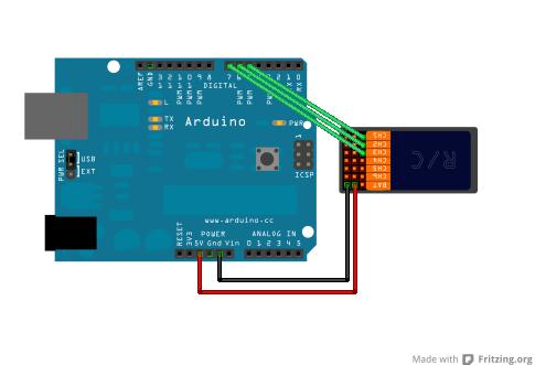
Notice that the RC receiver is upside-down, I flipped it to make it easier to trace my wires. You'll need to use male-female jumpers if you have them. If not, you can use some male and female jumpers stuck together. The digital pins that I chose are pretty much arbitrary; you should be able to use any digital input on the Arduino that you like, but the above should correspond to the code below.
Now let's upload a sketch and see what's coming in on those pins. The "servo" language that the RC receiver is pushing out is really PWM, or Pulse Width Modulation. Arduino has a handy function built in for reading these pulses and returning their length in milliseconds. This function is called pulseIn(). Let's take a look at a simple sketch I've written to print the raw input of the receiver to the serial monitor:
/*
 RC PulseIn Serial Read out
 By: Nick Poole
 SparkFun Electronics
 Date: 5
 License: CC-BY SA 3.0 - Creative commons share-alike 3.0
 use this code however you'd like, just keep this license and
 attribute. Let me know if you make hugely, awesome, great changes.
 */

int ch1; // Here's where we'll keep our channel values
int ch2;
int ch3;

void setup() {

  pinMode(5, INPUT); // Set our input pins as such
  pinMode(6, INPUT);
  pinMode(7, INPUT);

  Serial.begin(9600); // Pour a bowl of Serial

}

void loop() {

  ch1 = pulseIn(5, HIGH, 25000); // Read the pulse width of
  ch2 = pulseIn(6, HIGH, 25000); // each channel
  ch3 = pulseIn(7, HIGH, 25000);

  Serial.print("Channel 1:"); // Print the value of
  Serial.println(ch1);        // each channel

  Serial.print("Channel 2:");
  Serial.println(ch2);

  Serial.print("Channel 3:");
  Serial.println(ch3);

  delay(100); // I put this here just to make the terminal
              // window happier
}
The pulseIn() function takes three arguments: the first is the pin that your pulse is coming in on; the second is what type of pulse you're looking for; and the third takes a time-out number, which is how long you're willing to wait for a pulse. What this function returns is the length of the pulse in microseconds, and this is how we're going to read the incoming PWM as if we were a servo. When you run this code, you should get some numbers spitting out onto the terminal. The numbers probably won't mean much to you but they should be somewhere between 1000 and 2000. What really matters is that when you move the control surface associated with that number, it should change. If you don't know what channel each part of your transmitter is on, this is a good way to find out: just wiggle sticks, push buttons, turn knobs and flip switches, and take note of which channel is affected.
Now that we have these values, we can code with them and do all kinds of things. The sketch below is my sketch after it's been modified to put these pulseIn() values into context.
/*
 RC PulseIn Joystick
 By: Nick Poole
 SparkFun Electronics
 Date: 5
 License: CC-BY SA 3.0 - Creative commons share-alike 3.0
 use this code however you'd like, just keep this license and
 attribute. Let me know if you make hugely, awesome, great changes.
 */

int ch1; // Here's where we'll keep our channel values
int ch2;
int ch3;

void setup() {

pinMode(5, INPUT); // Set our input pins as such
pinMode(6, INPUT);
pinMode(7, INPUT);

Serial.begin(9600); // Pour a bowl of Serial

}

void loop() {

  ch1 = pulseIn(5, HIGH, 25000); // Read the pulse width of
  ch2 = pulseIn(6, HIGH, 25000); // each channel
  ch3 = pulseIn(7, HIGH, 25000);

  if(ch1>1000){Serial.println("Left Switch: Engaged");}
  if(ch1<1000){Serial.println("Left Switch: Disengaged");}
  /* I found that Ch1 was my left switch and that it
  floats around 900 in the off position and jumps to
  around 1100 in the on position */

Serial.print("Right Stick X:"); // Ch3 was x-axis
Serial.println(map(ch3, 1000,2000,-500,500)); // center at 0

Serial.print("Right Stick Y:"); // Ch2 was y-axis
Serial.println(map(ch2, 1000,2000,-500,500)); // center at 0

Serial.println(); //make some room

delay(100);// I put this here just to make the terminal
           // window happier
}
Here you can see that I've figured out which control surface on my transmitter is controlling which channel, and I've written a few print statements that will reflect my actions on the transmitter in plain English. You could expand this out to every channel on the receiver, you could also replace this sketch with Firmata and control a Processing sketch with your RC transmitter, but I think the best demonstration I can give is to slap this thing on a robot and drive it around. So let's get to it!
Radio Receiver Robot Rig?
I've chosen the Magician chassis and Ardumoto motor driver shield to be my robot platform for this project. Since it only has two wheels, it's a good way to demonstrate simple differential steering and how to mix everything to make it work. The first thing we're going to do is modify the Ardumoto shield to create an impromptu "RCMoto" shield by adding some headers to the prototyping header that we can plug our receiver into:
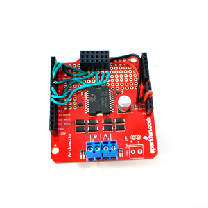
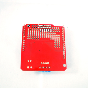
I made six rows of three, since my transmitter has six channels, and you shouldn't need to connect to the battery header on the receiver as long as you're running power and ground to the servo headers. When you solder these in, keep in mind that your receiver is going to go upside down on this rig, and wire it accordingly. You should be able to see how I wired this one by inspecting the pictures above. The ground row is all bridged together and plugged into ground -- same with the power row -- then each signal pin is broken out to a digital pin. This isn't the cleanest mod, but it works out pretty well. Here's what the robot chassis looks like with our modified Ardumoto Shield and RC receiver connected:
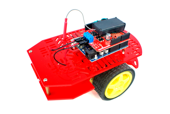
Not bad, right? Make sure that your motors are appropriately connected and add a power supply (9v battery worked fine for me), because it's almost time to drive this thing. Only step left is to write some code to translate servo steering commands into left/right motor commands. I'll give you the code now and explain it below.
/*
 RC PulseIn Joystick Servo Control
 By: Nick Poole
 SparkFun Electronics
 Date: 5
 License: CC-BY SA 3.0 - Creative commons share-alike 3.0
 use this code however you'd like, just keep this license and
 attribute. Let me know if you make hugely, awesome, great changes.
 */

int ch1; // Here's where we'll keep our channel values
int ch2;
int ch3;

int move; // Forward/Back speed
int turn; // Turning Factor

int pwm_a = 3;  //PWM control for motor outputs
int pwm_b = 11;  //PWM control for motor outputs
int dir_a = 12;  //direction control for motor outputs
int dir_b = 13;  //direction control for motor outputs

void setup() {

pinMode(5, INPUT); // Set our input pins as such
pinMode(6, INPUT);
pinMode(7, INPUT);

Serial.begin(9600); // Pour a bowl of Serial (for debugging)

  pinMode(pwm_a, OUTPUT);  //Set control pins to be outputs
  pinMode(pwm_b, OUTPUT);
  pinMode(dir_a, OUTPUT);
  pinMode(dir_b, OUTPUT);

  analogWrite(pwm_a, 0);
  analogWrite(pwm_b, 0);
}

void loop() {

  ch1 = pulseIn(4, HIGH, 25000); // Read the pulse width of
  ch2 = pulseIn(5, HIGH, 25000); // each channel
  ch3 = pulseIn(6, HIGH, 25000);
  /*
  if(ch1>1000){Serial.println("Left Switch: Engaged");}
  if(ch1<1000){Serial.println("Left Switch: Disengaged");}

Serial.print("Right Stick X:");
Serial.println(map(ch3, 1000,2000,-500,500));

Serial.print("Right Stick Y:");
Serial.println(map(ch2, 1000,2000,-500,500));

Serial.println();

delay(100);

clearAndHome();
*/

move = map(ch2, 1000,2000, -500, 500); //center over zero
move = constrain(move, -255, 255); //only pass values whose absolutes are
                                   //valid pwm values

/*What we're doing here is determining whether we want to move
forward or backward*/
if(move>0){digitalWrite(dir_a, 1);digitalWrite(dir_b, 1);};
if(move<0){digitalWrite(dir_a, 0);digitalWrite(dir_b, 0); move=abs(move);};

/*Here we're determining whether a left or a right turn is being
executed*/
turn = map(ch1,1000,2000,-500,500);
turn = constrain(turn, -255, 255);

/*This is where we do some mixing, by subtracting our "turn"
variable from the appropriate motor's speed we can execute
a turn in either direction*/
if(turn>0){analogWrite(pwm_b, move-turn); analogWrite(pwm_a, move);};
if(turn<0){turn=abs(turn); analogWrite(pwm_a, move-turn); analogWrite(pwm_b, move);};


Serial.print("move:"); //Serial debugging stuff
Serial.println(move);

Serial.print("turn:"); //Serial debugging stuff
Serial.println(turn);

Serial.print("move-turn:"); //Serial debugging stuff
Serial.println(move-turn);

Serial.println(); //Serial debugging stuff
Serial.println();
Serial.println();

}
Okay, let me see if I can explain how the steering happens in the above sketch. What I've done is basically mapped the forward/back direction of my control stick to a number between -255 and 255, with the former representing backward at full speed and the latter representing full forward. To communicate this to the Ardumoto shield, you have to break that out into two different numbers: direction and speed. To do that, I simply check to see if my number is positive. If so, I change the direction of both motors to 1. If the number is negative, then I just set both motor directions to 0. All I have to do after that is get the absolute value of the number and use it as my basic PWM value for both motors. I say "basic PWM value" because it's not actually what gets sent to both motors, instead a turn-rate is subtracted from one side.
To find my turn-rate and apply it, I map the side-to-side direction of the control stick to a number between -255 and 255, with the former representing a full turn to the left and the latter representing a full turn to the right. After I have that number, I find out which motor to apply it to. The way this works is by slowing down the motor on the side that we want to turn toward. This method will never produce a zero-radius turn, but it works reasonably well. Again I check to see whether my number is negative. If so, I subtract the absolute value of the turn-rate from the left motor's speed. If it's positive, I subtract the absolute value of the turn-rate from the right motor's speed.
There are obviously other ways to implement differential steering; with a little more code you could reverse the appropriate motor and turn in place. Also, this code doesn't steer the way you might expect when driving in reverse. At any rate, this should get you started with Radio Control robots, and I hope that you've been inspired to grab a hobby transmitter for your next robot project!
Happy hacking!
It is a bit old now, but i wrote a library to use interrupts instead without the need of understanding interrupts. Just check it out on Github: https://github.com/timoxd7/FastRCReader
Use the interrupt luke:
(well, my code was easier but too long to be here so...)
http://code.google.com/p/aeroquad/source/browse/tags/AeroQuad_v2.4.3/Receiver.h
can you help me can you program me on 4 channel 1 channel is to manual en automation en 1 channel for gas servo 1 channel for rudder can you help mee jcantuba@gmail.com
Here my code: https://github.com/lestofante/arduinoSketch/tree/master/ClassPPM The code read the PPM on pin 2,4,5,6 and put in in a array. The value can be retrived with inputs.getDuration(X) where X is the POSITION IN THE ARRAY, witch is set in the ISR in InputPin.cpp
I think it would be useful to mention in this tutorial how to read the rc receiver using interrupts on the arduino. Reading them through the pulsein function works but is really not the quickest method.
Thanks Nick, just what I was looking for!
Hi Like Your Post but I'm 83 years old and no nothing about codeing etc. I just built a 1918 fordson tractor and need to run the mo tor forward and backward and operate a servo for steering where can I find a simple Radio controlled example for that ?
Hi there, it sounds like you are looking for technical assistance. Please use the link in the banner above, to get started with posting a topic in our forums. Our technical support team will do their best to get you pointed in the right direction.
Unfortunately, we don't really have a simple guide/product for that. Without having to learn to code... the best I could recommend, is most hobbyist RC products use an RF remote and transceiver that usually interfaces with a servo. Also, maybe try visiting a hacker/maker space in your area to recruit someone with hobbyist RC experience.
I would like to use an arduino UNO to control portions of a home made RC submarine. Specifically, switch channels 5 and 6 from my futaba FP-R127DF receiver. I used your code to learn my pulses are 955 when switch is off and 2061 when on. Can you help me create a code to have the uno recognize when switch is on or off and then send something to output to a PWM relay such as this: https://www.amazon.com/gp/product/B07BS6PCR6/ref=ppx_yo_dt_b_asin_title_o02_s00?ie=UTF8&psc=1 I am attempting to use channel 5 on my transmitter to activate the relay to connect 12V to a solenoid valve (open MBT) and channel 6 to connect 12V to a solenoid valve and air pump (Hi pressure air to MBT). The relay has 2 settings, HI and low, Hi will not do anything when the receiver is connected direct to the relay, and if the jumper is in Low position, the relay is activated regardless of switch position. So I figured I could use the arduino to control my ballast tank system. I am new to arduino and only know how to flash a bootloader to my ender 3 pro 3d printer, right now it is programmed with your first code to find the PWM numbers. Can you help me with my little dilema?
Hi there, it sounds like you are looking for technical assistance. Please use the link in the banner above, to get started with posting a topic in our forums. Unfortunately, this is outside the scope of our technical support team; we don't provide contract-based services. However, hopefully, someone in the public community will be able to help you out. Otherwise, using a search engine like Google to find/narrow down resources is great.
Thank you so much nick this help me a lot to figure out PWM receiver. mine was showing so much noise on each channel but letter i figured out that, that was due the power source I was using; which was the PWM power supply and disturbing the receiver, when I use the Arduino to power receiver and uploaded your code there was no noise at all. Thank you so much.
Awesome! I found this on my first hit on this topic. Don't get me wrong, I WILL be doing this in my project. However, I'm asking myself ... Am I just building an R/C car and if so, why would I even bother with an Arduino!? :-) As far as miixing ideas, mine will use the Y axis to control the throttle and X axis will determine the percentage mix of left and right motors ... i.e. hard left or right will be 100% one motor. R/C transmitters these days can program mixing and rates. I think the X/Y mix will be in the Arduino and the exponential rates would be easier to adjust in the transmitter. Exponential follows an logarithmic scale vs a linear scale.
Another mix you could use your brain. You'd control with 2 sticks like a bobcat or zero-turn lawn mower. That would be cool because you could have one motor forward and the other reverse to do a spin in place.
Not sure if this thread is still very active, but i was wondering how you might turn the inputs to a digital on/off signal? I've been working on building a rc car for a while now, and have decided to run the lights for it via the arduino and leave the steering and forward/ backward motion to a motor controller (the servo for steering can plug directly into the receiver). I'm using a rc controller for a quad copter so i have extra channels ( 2 aux if i don't use the side ways functions on the joysticks). I'm ting to turn on neopixles under the car from 1 channel, and from the other channel headlights/ tail lights, but, (I can't figure out how to get the arduino to reliably interpret the pwm signal as an on/off signal.
The reason i'm not running the whole thing with an arduino is because i need to run the wheel motors on 12V 3A and couldn't find a good way to do that without using a relay and having the motors full on or full off, and i couldn't figure out the interrupt pins to turn the aux functions on at any time.
Any advise? it would be greatly appreciated.
Many thanks!! ..
maybe not the fastest one.. but can't be more simple... :D now i can use my FS-i6 to drive my bluetooth RC drift car :D
by the way i replace the 25000 with 30000 now the readings without (not so) random 0
If you are going crazy with using 3 or more channels. Don't worry, I got you. If the serial console shows just some of the channels and all the wiring on your Arduino is correct, probably your problem will be solved just below. I came up with a nice reception of 6 channels by using the function this way: pulseIn(13, HIGH); By deleting this, by default Arduino uses a 1sec timeout. (very annoying but useful & gives you an idea...). With this info in mind and this reference https://www.arduino.cc/en/Reference/PulseIn I bet you can solve the problem.
Hint: Its something involved with the timeout and PWM generated with your reciver :D
Another solution is using @JamestheQuack method.(scroll down , don't be lazy)
// it works only 1 servo ...why not 2 servo work properly...i just modify the code average valu for servo jliter
void Servo_Control1(){ int Pos1; inputPina = pulseIn(42, HIGH, 25000); // /Servo 2 Pos1 = map(inputPina, 1000, 2000, 0, 180); //center over zero Pos1 = constrain(Pos1, 0, 170);
totala = totala - readingsa[readIndexa]; readingsa[readIndexa] = Pos1; totala = totala + readingsa[readIndexa]; readIndexa = readIndexa + 1; if (readIndexa >= numReadingsa) { // ...wrap around to the beginning: readIndexa = 0; }
averagea = totala/ numReadingsa; Serial.println(averagea); myservo1.write(averagea); delay(1); }
void Servo_Control2(){ int Pos2;
inputPinb = pulseIn(44, HIGH, 25000); // /Servo 2 Pos2 = map(inputPinb, 1000, 2000, 0, 180); //center over zero Pos2 = constrain(Pos2, 0, 170);
totalb = totalb - readingsb[readIndexb]; readingsb[readIndexb] = Pos2; totalb = totalb + readingsb[readIndexb]; readIndexb = readIndexb + 1; if (readIndexb >= numReadingsb) { // ...wrap around to the beginning: readIndexb = 0; }
averageb = totalb / numReadingsb; Serial.println(averageb); myservo2.write(averageb); delay(1); }
im following ur code ... but im using flysky th9x reciver my problem is when i add pen til servo on it ... it only work 1 servo ... why dont i use 2 servo same time
is it possible to make an arduino have wireless controls or does all that come from the receiver? i have a arduino that has 22 channels on it and i want to get it to go wireless but i dont know of any receivers that have 22 or more channels. can i just make the board have a built in receiver?
Hello. I am working on an electric bus project and I have been using a joystick connected to a motor controller to control the dc motors on the prototype. However, I want to control the motors now using a RC remote and an arduino to control the motors via the motor controller. I havent done this before and I am not sure which RC remote will be best for an application like this. The movements needed are for left,right, forward and backward. Can you please suggest a RC transmitter and receiver that will best be used with the Arduino. Thanks for the great work
could some one please help me with a pinout between the VNH2SP30 + Arduino UNO + RC Receiver (FrSky).
i could make the motors work with L293D but with this VNH2SP30 board i am totally lost.
want to use the code above...
appreciate your help...
Hey npoole thanks for posting this! It was very helpful. I couldn't find your code on Github (the git urls in prior comments were broken or for different libraries), so I posted your last block of code in my github account: https://github.com/mikezawitkowski/RCJoystickServoControl I'll keep adapting it for my own purposes so it will change considerably, but anyone who needs a fresh starting point can roll back and choose the very first committed file version. If you have a github repo or some other reference you want me to include in the attribution, just let me know!
Thanks I know this is an old article but here are my comments I will use this as a base for panic switch on an airplane. I will include an accelerometer in the circuit and code. In normal mode the signals from the receiver will pass through. When a signal is received on the "panic" channel the receiver signals will be suppressed and the input from the accelerometer will be converted to PWM and sent to the servos to bring the plane back to a stable flight
This code works when using the old Arduino IDEs like 1:1.0.5; it does not work using 1.6.5?! I noticed that it receives the first channel the code reads and returns 0 for the second channel. It also yields different ranges of PWM signals (or periods of time). Very strange. If you want to make use of this, and are being frustrated, hunt down an older IDE (until this gets fixed on the Arduino side). James
Look my recent comment, it appeals your problem !!
Hi, I have been trying to do this for months!! My problem, I am using a stepper motor, which I can control the speed using a 10k pot, and mapping the analog input from the pot to a range of 0 to 100. Can I map the digital input from the RC receiver in a similar fashion to control the speed? Remembering that my RC receiver is SINGLE direction only.
Thanks
Mick
Cool
Hi, im new to arduino and i have a 6 channel rc system, so i want to control 3 motors that turns forwards and backwards , can someone help me please? i dont even know where to start hehe, thanks
This is really not the quickest method. This will for example not work for a quadcopter. It will only work for demo purposes. I have interrupt code working, but unfortunately for you, it is avr-gcc code which does not use arduino ide. Nontheless, it is part of my driver code for the multiwii board as part of the overall driver framework.
You can see the code here: https://github.com/mkschreder/martink/blob/master/boards/multiwii.c
HI. I have a model RC submarine and I am programming arduino to fire a few relays to manage the ballast system. I have don all this, but the whole purpose of this is to automate a dive and surface routine, and the issue I have is how to trigger the routine. I would like to quickly double click the transmitter joystick over, within say 250, and for this motion to turn on a subroutine. i am having great trouble coding this. Is there any help for this?
Hello, I wanted to ask if its possible to program raspirobot in C++ and from where can i get the libraries for this purpose. I only have found the python library so far.
Regards
Nick... Thank you... So much...
Hi: I took your guide and I'm doing basically the same. But the motor runs at half the speed. I mapped the input pulse from 1000,2000 (I added calibration feature so those values may change) to -500,500, tries with ...,-255,255 but it still runs at barely half the speed.
I'm using a Nano and a L293B. Everything goes fine, direction, neutral, but the speed.
I'd appreciate any help. Robert
Whenever I have ran into a speed issue using PWM, it has been the PWM frequency that was set incorrectly. The reason your motor turns slowly while at 100% duty cycle is because the pulse, or Frequency is too looooooooooong of a period for 1 pulse. It needs a higher frequency resulting in a faster pulse (Shorter width at 100% duty) which will give you your speed.
Here is some code to change the frequency of Timer1 (Pins 9 + 10) on an ATmega32U4 based microcontroller (Leonardo, Pro Micro...) Code was adapted from the best tutorial on PWM I found here: http://r6500.blogspot.com/2014/12/fast-pwm-on-arduino-leonardo.html Code is for a pitching machine I repaired. Had a 10K pot for speed input.
How would one reverse this? Is it possible to have just the receiver connected to the device and remotely sending the commands to it via RF or Bluetooth or something along those lines?
Ok maybe i am just stupid or something but were can i find/buy the radio receiver using in this project i can't find a link anywhere and have spent hours on spark fun website
Go to this website and there's some really cheap radios.
hi could you help me adapt this to the rover 5 and rover 5 motor controller with only two motors...tryed using it but got no movement from bot .. may be im wiring it wrong
is it possible to control a wheeled robot..actually a wall climbing robot based on suction mechanism...using this one..??? it got to move in all four directions..!!
What does "You'll need to use male-female jumpers if you have them. If not, you can use some male and female jumpers stuck together" mean?
This is such a great project. Someone was asking about a similar project on TechXchange last week: http://www.digikey.com/techxchange/thread/4150
I'd like to share with you a little mod on this code.
Connected to the Throttle / brake channel of the reciever, it will detect when you hold the brakes on your transmitter. Then it will turn ON the brake lights!
(a bit too simple, I know, but it was my first approach to Arduino)
/* ************************************************************** Modificación del código "RC PulseIn Serial Read out" By: Nick Poole (SparkFun Electronics) License: CC-BY SA 3.0 - Creative commons share-alike 3.0 */ // lectura de entrada desde receptor RC, para activar luz de freno. // // By Pentiumcadiz // // http://www.youtube.com/watch?v=JdMYpq1Mus8 //
int pin_entrada = 7; // pin en el leemos la señal que viene del receptor unsigned long pulso; // variable en la que almacenaremos la lectura int salida = 13; // pin de salida para LED(s)
void setup() { pinMode(pin_entrada, INPUT); // configuramos el pin D7 como entrada pinMode(salida, OUTPUT); // configuramos el pin D13 como salida Serial.begin(9600); // habilitamos puerto serie }
void loop() { pulso = pulseIn(pin_entrada, HIGH); // leemos el pulso
//Si está frenando if(pulso < 1400) //´Teóricamente es 1500, pero doy 100 de margen. { // turn LED on: digitalWrite(salida, HIGH); // Luz de frenos encendida } else { // turn LED off: digitalWrite(salida, LOW); // Luz de frenos apagada }
// Sólo durante las pruebas, muestro la lectura del Rx, para comprobar los valores. Serial.println(pulso); // mandamos el dato al monitor serie delay(300); // pausa para no volver loco al monitor serie }
how i can set x and y for all channels ?
how i can make that the serial shows me when i move the right button ??
Hi, The code presented here has a number of problems, I understand that it is simply an introductory example however for a solution that addresses the problems see here -
http://rcarduino.blogspot.com/2012/05/interfacing-rc-channels-to-l293d-motor.html
For those that mention it, it also uses interrupts although in the case of a slow moving robot pulseIn could work just as well - until you start adding additional inputs, encoders etc.
The link also allows correct proportional speed and steering in forwards and reverse and also allows rotation on the spot.
Duane B
rcarduino.blogspot.com
Using interrupts is better ! I made the same thing few month ago, in order to diagnose receivers outputs : http://www.youtube.com/watch?v=oY1-du-HGQY Then, I replaced the serial bridge in the 8u2 with an HID joystick one, so I can use my remote control as a joystick on any computer for virtual racing. It just requires some software flow control in the serial link between the 328p and the 8u2 to avoid buffer overflow.
I didn't see any mention of where to purchase or which reciever was used. (If it was mentioned in the code sections, I can't read them as they don't show completely in android.)
basically, i think they are refering to any hobby grade tx/rx system. but, as an avid RC'er, i would like to point out that even the the industry standard for the frequency is in the 2.4ghz range, pretty much EVERY radio manufacturer has their own proprietary system: i.e. Spektrum has DSM, Futaba has the FAAST and FHSS. this can make receiver buying a pricey ordeal, since there are very few aftermarket receivers for either the Spektrum or Futaba radios. your best bet for a decent 2.4 radio with pretty inexpensive receivers is to get a FlySky system. these are readily available through either hobbypartz.com or on hobbyking.com (on HK they are branded as hobbyking brand.)
ArduPPM is a quite mature RC PWM decoder system (developed as part of the ArduPilot project) and the source (in the ardupilot source repository) is quite useful to have a look at.
Also, if your RC receiver has a PPM output (and there are tutorials around on how to hack one in if it doesn't) that's even easier to read in, and you can get every channel using just one input pin on the arduino.
I can't get the sketches to compile.
sketch_may23a.cpp: In function ‘void clearAndHome()’: sketch_may23a.cpp:46:18: error: ‘BYTE’ was not declared in this scope
check the tutorial again. it's an error because you're using arduino 1.0. you have to set the variable as a byte first, then print it. removing that line allows it to work.
I don't know if the cost of two xbees and another Arduino would be more or less than buying an RC transmitter and receiver. (If you already HAVE an elcheapo RC TX and RX left over from a cheap toy that got smashed then no. But if you had to buy just the transmitter and receiver it might be a wash.) In my case I started with two Arduinos and two xbees. I tried to hook a joystick up to the analog inputs of one xbee and receive the output on the second but there was a HUGE time lag between moving the joystick and seeing the corresponding change on the receiver. One or both xbees were buffering a lot of data from the A/D converter. So I used one Arduino to perform the A/D on two channels and send the data (in binary) to the xbee to transmit. On the receiving end I did pretty much the same thing done here to control two motors except I didn't need to analyze pulse widths as the required number was figured on the transmit end. I was using the 900mhz xbee's BTW, we just thought we might get more range on the lower frequency and we didn't need the extra BW.
A 2.4GHz TX/RX package on another hobby website is ~$25. You don't need anything else to get wireless in to your project. I'm going to figure that the cost of two xbee's is going to be more than that, but I am not even going to check I am that confident.
XB has its uses, but for super-simple and cheap wireless control (not for getting any data back) you absolutely cannot beat hobby TX/RX for price and range.
with the xbee just try to force the flush of the output. There should be a command, if not, the buffer size should be 32 char... :)
a 6channel 2.4GHz RX/TX can be bought at 25$ (see hobbyking), it cannot carry data, but it is fast, with a long range, anti-collision, and steal low bandwidth.
Great tutorial, Do you have a movie to show how much is faster the communication between Arduino and the remote control? I was building something similar but over Wifi, I had some problems with my driver controller.
Not sure if this page is still active or not but does anyone have some schematics of this project; I'm confused on where to solder the connections on the motor shield and connecting it to the Arduino board and the RC receiver. The pictures above are really blurry for me and confusing. Thanks in advance!
How could I make a 4WD car with a receiver?