- Home
- Product Categories
- Arduino Shields
- SparkFun Ardumoto - Motor Driver Shield

SparkFun Ardumoto - Motor Driver Shield
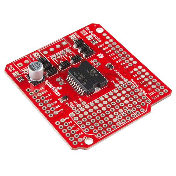
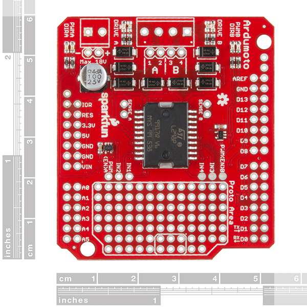
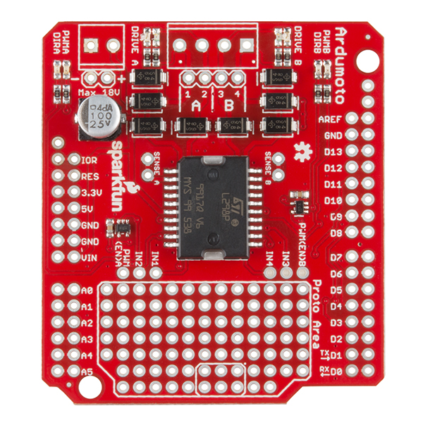
The Ardumoto Shield is a dual-motor controller for Arduino. Based on the L298 H-bridge, the SparkFun Ardumoto can drive two DC motors up to 2A per channel. Combined with an Arduino, the Ardumoto makes a fantastic controller platform for RC vehicles or even small autonomous robots. It’s now easier to use, featuring control signal LEDs, while also being much more flexible for advanced users.
The board takes its power from the same Vin line as the Arduino board and includes blue and yellow LEDs to indicate active direction. All driver lines are diode protected from back EMF. The L298 is a two-channel motor driver, which means it can individually drive up to two motors, making it perfect for a two-wheel-drive vehicle. Each channel on the L298 can deliver up to 2A to the motor to which it’s connected. Keep in mind, though, that the amount of current available to your motor also depends on your system’s power source.
Note: The Ardumoto does not include screw terminals or stackable headers; you will need to purchase both separately. You can find them in the aforementioned links or in the Recommended Products below.
SparkFun Ardumoto - Motor Driver Shield Product Help and Resources
Ardumoto Kit Hookup Guide
April 14, 2017
Learn how to assemble and drive DC motors using the v2.0 Ardumoto Shield.
Core Skill: Soldering
This skill defines how difficult the soldering is on a particular product. It might be a couple simple solder joints, or require special reflow tools.
Skill Level: Rookie - The number of pins increases, and you will have to determine polarity of components and some of the components might be a bit trickier or close together. You might need solder wick or flux.
See all skill levels
Core Skill: Robotics
This skill concerns mechanical and robotics knowledge. You may need to know how mechanical parts interact, how motors work, or how to use motor drivers and controllers.
Skill Level: Rookie - You will be required to know some basics about motors, basic motor drivers and how simple robotic motion can be accomplished.
See all skill levels
Core Skill: Programming
If a board needs code or communicates somehow, you're going to need to know how to program or interface with it. The programming skill is all about communication and code.
Skill Level: Rookie - You will need a better fundamental understand of what code is, and how it works. You will be using beginner-level software and development tools like Arduino. You will be dealing directly with code, but numerous examples and libraries are available. Sensors or shields will communicate with serial or TTL.
See all skill levels
Core Skill: Electrical Prototyping
If it requires power, you need to know how much, what all the pins do, and how to hook it up. You may need to reference datasheets, schematics, and know the ins and outs of electronics.
Skill Level: Rookie - You may be required to know a bit more about the component, such as orientation, or how to hook it up, in addition to power requirements. You will need to understand polarized components.
See all skill levels
Comments
Looking for answers to technical questions?
We welcome your comments and suggestions below. However, if you are looking for solutions to technical questions please see our Technical Assistance page.
Customer Reviews
0 out of 5
Based on 0 ratings:
I think I experience a pretty big voltage drop over the output (i get 10,9V from a 12V PSU); is it expected I have the first version. I wish I knew this before building my project, probably should be advertised. I power 12V gearmotors and they seemed slower than usual. I use it with an arduino nano and the max voltage is 12V so I can't really up the PSU to 13-15V to compensate; I'd have to power the arduino separately. bummer.
I need more information about how to use the Proto Area. How are components soldered onto the Proto Area connected to the Arduino and what is the programming involved? Thanks.
It is just a bunch of PTH holes that are not connected to anything. You will have to wire them to the Arduino yourself (probably running a wire from the proto area to the extra row of shield headers). Check out the hookup guide for more information as there is a whole section that goes over the proto area.
I used the previous version of this shield in one of my projects: http://limerick.pulserain.com/2017/07/how-to-build-lego-monster-truck.html
Now I'm trying to use the new one (DEV-14129) to replace the old one (DEV-09815) for another project. The difference between those two versions are:
a) The pin assignments are different. The new one uses pin 2 and pin 4 to control the rotation direction, while the old one uses pin 12 and 13
b) The new one added some LEDs with 1K ohm resistors on the IO pins directly to show signal activity. However, this will cause problems for some Arduino compatible boards, because those boards often support dual voltage IO (3.3V/5V). So the IO outputs are OD (open drain) instead of totem-pole. And the 1K ohm resistor on the new shield will pull the voltage below its threshold. To use the new shield for my project, I have to have those 1K ohm resistors removed.
Following information is missing:
Max voltage without modifications is 18V (Sparkfun, you should make the connection to Arduino Vin disconnectable and C3 rated for 63V, so it can be used up to 40V, as is allowed by the chip)
4A?? Mine reaches 60°C on top of driver chip (ambient 26°C) with a continuous load of 100mA per channel. Please provide realistic current figure or improve board layout. Even better, make a mosfet-based one.
The static tests I did while designing shows the following steady state limits at rated voltage:
I'll see about changing the description to say 'peak' rather than 'up to'. I agree that's a little misleading, but most people aren't trying to regulate 160W of drive continuously! I do have some plans to make that product in the future though.
If you want the full current capacity at steady state, you'll have to remove the heat from the IC by way of a heatsink or by forcing air (better yet, do both!) Even a light breeze helps tremendously.
I get different results with the 100mA current test. I drive 113mA/channel and get 35°C with an 8V source, or 40°C with the full 18V source (ambient 27°C, laying flat on desk). Are you running yours from 40V for your 60° results?
I did forget to mention that I was running it at 24V, which is above your 18V rating. Replaced the cap and cut the trace to Vin. Arduino was run from separate supply. It was also used with another shield on top, which doesn't help the convective cooling of course.
Maybe add your 1.1A continuous figure to the description, with the test conditions, that gives people more of an idea what to expect:)