Diffused LED - RGB 10mm
COM-11120
Diffused LED - RGB 10mm
SKU: COM-11120
$1.95
In stock
SKU
COM-11120
Product Overview
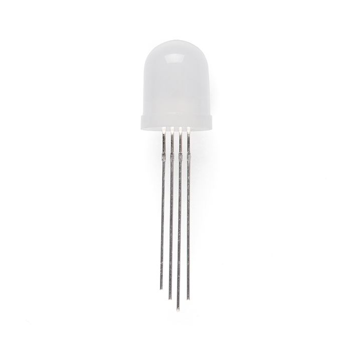
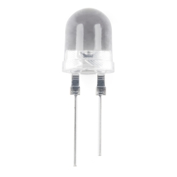
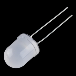
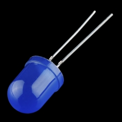
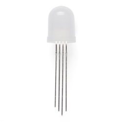
Check out these big 10mm through-hole LEDs! The opaque epoxy package causes these LEDs to have a soft, diffuse glow.
Features:
- Forward Voltage (R/G/B): 2.0 / 3.2 / 3.1V
- Forward Current: 20mA
- Intensity (R/G/B): 550 / 250 / 700 mcd
- Common Cathode
Documents:
Similar Items

Hookup Accessories


Features & Specs
- Forward Voltage (R/G/B): 2.0 / 3.2 / 3.1V
- Forward Current: 20mA
- Intensity (R/G/B): 550 / 250 / 700 mcd
- Common Cathode
Documentation
Customer Reviews
Diffused LED - RGB 10mm
$1.95
COM-11120
Stock and Customer Discounts
$1.95 retail price.
Available Discounts
- $1.85 | 25+ units
- $1.76 | 100+ units