SparkFun USB to Serial Breakout - FT232RL
BOB-12731

SparkFun USB to Serial Breakout - FT232RL
SKU: BOB-12731
$22.95
In stock
SKU
BOB-12731
Helpful Documentation
 Schematic
 Datasheet (FT232RL)
Product Overview
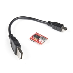
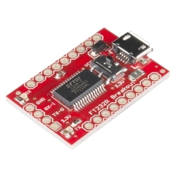
This is the SparkFun USB to Serial Breakout for the FT232RL, a small board with a built in USB to serial UART interface. This little breakout is built around the FT232RL IC from FTDI, with an internal oscillator, EEPROM, and a 28-pin SSOP package this is a serious little chip.
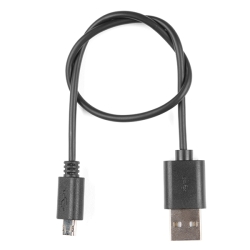
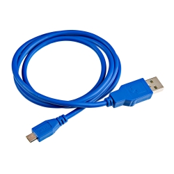
With this version, we've corrected a few issues found with the board. These changes include fixes to the VCCIO, a change from the mini USB to micro USB connector, and a few footprint modifications. Other than finding this board much easier to use, it is still the same FT232RL breakout that you know and love!
Similar Items


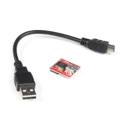
Hookup Accessories


Features & Specs
- Implements full v2.0 USB protocol
- Needs no external crystal
- Internal EEPROM for device ID and Product Description strings
- Royalty-Free Driver support for Windows, Linux, and Mac OSX
Customer Reviews
SparkFun USB to Serial Breakout - FT232RL
$22.95
BOB-12731
Stock and Customer Discounts
$22.95 retail price.
Available Discounts
- $21.80 | 10+ units
- $20.66 | 25+ units
- $19.51 | 100+ units