- Home
- Product Categories
- RFID Readers
- SparkFun RFID USB Reader

SparkFun RFID USB Reader
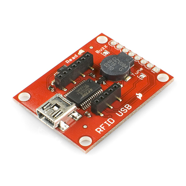
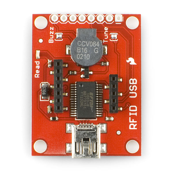
The SparkFun RFID USB Reader is a simple to use, USB to serial base unit for the ID-3LA, ID-12LA, and ID-20LA readers. Simply plug a reader into the headers and attach a miniUSB cable. Open a terminal program of your choice at 9600bps 8N1, then scan your 125kHz ID tag and the unique 32-bit ID will be shown on the screen. The unit is based on a FTDI chip and comes with a read LED and buzzer.
This new revision uses SMD headers for the RFID module, and has a solder jumper which allows you to disable or enable the buzzer.
Note: This product does not come with the RFID reader. Check below for compatible readers.
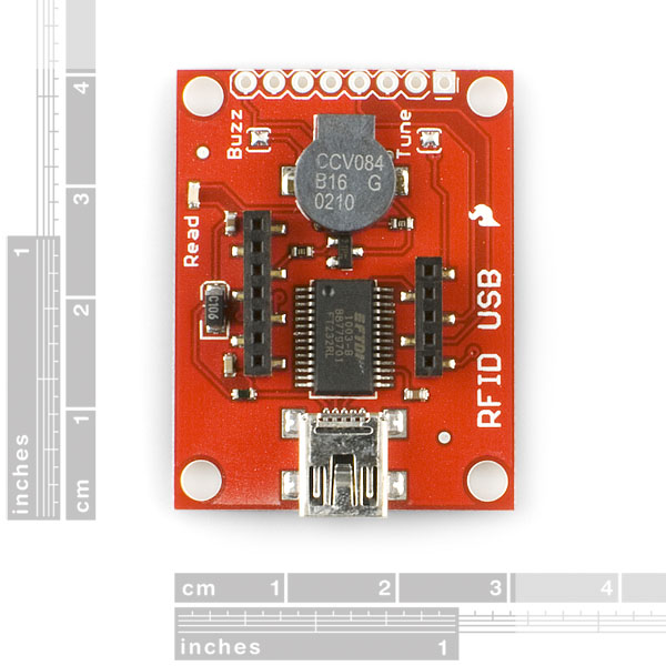
- 1.4x1.2x0.57"
SparkFun RFID USB Reader Product Help and Resources
RFID Basics
February 23, 2017
Dive into the basics of Radio Frequency Identification (RFID) technology.
Read Ranges Using the RFID USB Reader
Using the ID Innovations125kHz readers, the tested real world maximum ranges of the modules with the RFID tagged items are listed below:
ID-3LA
Card = 0" (you need an external antenna)
Button = 0" (you need an external antenna)
Glass Capsule = 0" (you need an external antenna)
ID12-LA
Card = 2" - 2.25"
Button = 1" - 1.5"
Glass Capsule = 0.75" - 1"
ID20-LA
Card = 2.75"
Button = 2"
Glass Capsule = 0.75"
The range results were taken from the demo video between 6:13-9:10 => https://youtu.be/FLjV5BT9slg?t=6m13s .
Multiple RFID USB Readers
If you place 4 of these RFID readers with the ID Readers, there will be RF interference from each other. Customer had issues with this setup. When he placed them at a distance of about 15-20cm+ between each other, they were able to get them working.
Core Skill: Soldering
This skill defines how difficult the soldering is on a particular product. It might be a couple simple solder joints, or require special reflow tools.
Skill Level: Noob - Some basic soldering is required, but it is limited to a just a few pins, basic through-hole soldering, and couple (if any) polarized components. A basic soldering iron is all you should need.
See all skill levels
Core Skill: Programming
If a board needs code or communicates somehow, you're going to need to know how to program or interface with it. The programming skill is all about communication and code.
Skill Level: Rookie - You will need a better fundamental understand of what code is, and how it works. You will be using beginner-level software and development tools like Arduino. You will be dealing directly with code, but numerous examples and libraries are available. Sensors or shields will communicate with serial or TTL.
See all skill levels
Core Skill: Electrical Prototyping
If it requires power, you need to know how much, what all the pins do, and how to hook it up. You may need to reference datasheets, schematics, and know the ins and outs of electronics.
Skill Level: Noob - You don't need to reference a datasheet, but you will need to know basic power requirements.
See all skill levels
Comments
Looking for answers to technical questions?
We welcome your comments and suggestions below. However, if you are looking for solutions to technical questions please see our Technical Assistance page.
Customer Reviews
4.4 out of 5
Based on 8 ratings:
1 of 1 found this helpful:
Pin layout needs upgrade
Currently this device has a connection to the card present pin 5 of the ID-12LA unit, but this is not very useful. The ID unit is set to ASCII output, not Magnetic card emulation, therefore this breakout board should have the "tag present" pin (pin 6) wired to the board not pin 5 (which is only active in Mag. Card Emulation). In the datasheet, pin 6 is labelled as "Future", but the future has arrived...this pin goes high when a tag is present, and goes low when the tag is removed. This board should be upgraded for this functionality.
1 of 1 found this helpful:
Some readers need an antenna
The ID3-LA requires an antenna. Pay close attention to which reader you get to go with this board.
Working great, I am happy with this.
Simple RFID reader that's easy to program
I'm using this to lock and unlock a Z-wave electronic doorlock. I'm quadriplegic and have the tag mounted on the footplate of my wheelchair. I have one reader inside the house and the other outside. I use the ID-20LA reader which together with the credit card tag has a range of about 3" which is just about perfect. I connected it to a raspberry pi and wrote the software in python. Here's the link to my YouTube video, and the project will be on GitHub real soon now. http://youtube.com/watch?v=-B-Js19Npv0
Bravo! Thank you for sharing your video.
Responsive and easy to use
The SparkFun RFID USB reader is responsive and easy to use.
I was able to use it to read RFID tags: - with a ESP32 board: https://wp.me/p245TQ-uB - with Python 3: https://wp.me/p245TQ-v4
Delivery of item was fast too.
Very useful but could be better
I wish this circuit could have more breakout pins available to solder. I use the ID-12LA reader and on it, there is an specific pin that I think it is useful. The number 6 pin (Tag in Range). Using this pin, you can tell when a tag is placed near the reader (0), and when the tag is far from the reader (1).
After trying a few options, this is one the one we went with!
RFID tech can be tricky but using this with the Sparkfun Antenna has been a perfect combo. Good, clean reads with all our RFID chips has made life much easier for us!
-------------------- Tech Support Tips/Troubleshooting/Common Issues --------------------
Read Ranges Using the RFID USB Reader
Using the ID Innovations125kHz readers, the tested real world maximum ranges of the modules with the RFID tagged items are listed below:
ID-3LA
ID12-LA
ID20-LA
The range results were taken from the demo video between 6:13-9:10 => https://youtu.be/FLjV5BT9slg?t=6m13s .
Multiple RFID USB Readers
If you place 4 of these RFID readers with the ID Readers, there will be RF interference from each other. Customer had issues with this setup. When he placed them at a distance of about 15-20cm+ between each other, they were able to get them working.
Folks, Can I power it with 3.3V using an Arduino Fio?
I'm having trouble getting this to work with my arduino. I have the vcc connected to 5V, the grnd to grnd. and the tx is connected to the rx.
I'm using an Arduino Uno. I'm pretty new to all of this. Basically trying to get an RFID to trigger an LED and a Piezo speaker.
Any nudges in the right direction would be helpful.
Thanks!
Sorry to bump a reeeally old thread, but have you tried unplugging your TX-RX line on the Arduino from the chip to the board wen you're uploading a new sketch? Sometimes the system glitches out b/c of weird serial things, but unplugging that solved my problems.
Il have the same problem of you.
I recently purchased an id-12 kit to see if I could use a key fob from my workplace with it. The key fob is an HID Proxy card and it uses the 125kHz frequency. Unfortunately it will not read the HID card. I read that some cards use a protocol where they don't broadcast their ID for security reasons. I'm guessing that is the case with the HID card. Is it possible to get the ID-12 to read these types of rfid cards? Does anyone have any experience with similar cards? -thanks in advance
I second that... Wish it would work. Maybe (just my speculation) the facility ID is different. Or the reader broadcasts a signal to tell the tag to broadcast its code.
Is there any reason why the RESET pin isn't broken out? It seems like you should be able to trigger a read by toggling that pin. (eg: to see if the card that was read a second ago is still in range). Am I wrong about this? Please let me know before I start soldering on this board unnecessarily :)
agree. RESET is not broken out. I cut a trace and soldered a flywire onto the exposed pad, that works fine, but sheesh what a pain.
According to the docs for the ID-20LA: "Pin6 is used as a ‘Tag in Range’ indicator. When a tag is in range the pin is set to VDD voltage else it is at 0v. Pin6 output has an internal 3K3 resistor and may be used to drive an LED directly."
Naturally, Pin 6 is not connected on the breakout board either. But it does function as advertised, going high when a tag is first read and staying high until the tag is out of range, at which point it goes low. Perhaps easier than having to cut a trace, but you still have to solder onto the pad.
In the same need: an on-board software RESET function. In order to have the reader put out a new reading, to check up whether the tag is still there or not.
This USB breakout is very comfortable and working quite fantastically, unfortunately a software reset function seems to be missing. I have searched the net for some hours now to find someone who pulled the trick doing some sort of a SOFTWARE RESET through the USB board directly, but no success yet.
It would be great to do something like Serial.write("reset"); to probe the reader for a new reading.
SPARKFUN, could you confirm this software reset is or is not available on the RFID USB Breakout?
If not available, would there be way to make a HACK to the board so no external microcontroller is needed to make the Reset happen?
Thanks a lot!
ps. board ordered through http://www.antratek.nl/RFID.html (Europe, NL)
I see that it "has a solder jumper which allows you to disable or enable the buzzer' but how exactly do I do that? I see the little "Buzz" written on the board. Do I have to un-solder that? Or connect it to something else?
I tried connecting VCC to GND but.. that clearly was not the way to go as it immediately fried the thing...
Does anyone know if it's possible to route pin 7 of the ID-12LA to VCC to put the reader into Weigand mode, and will the ID-12LA still talk to the FDI chip? Or can one jumper it to pin 10 for Magnetic Emulation Mode? I'd like to try these out. That would be a nice feature for the next revision - in the mean time, has anyone tried cutting the trace from pin 7 and jumpering? Thanks!
It works well if i connect it to a raspberry pi? Are driver compatible or downloadable easily?
Any word on when the replacement for the non-USB version, SEN-08423, will be back in stock?
Is there any way to read the CP/Card Present line over the USB/FTDI?
Answer via schematic. No there is not.
Hi I would like to know if this is compatible with RFID Module - SM130 Mifare (13.56 MHz) and RFID Evaluation Shield - 13.56MHz?
If yes, do I just plug them in and link them together? If no, how can I connect the RFID Module to the computer via usb?
Many Thanks!
I wrote some code (https://github.com/Andrew67/RfidTap) that basically turns the serial port input into an HTTP server that you can poll using cross-site AJAX which returns the ID (Tested with ID-12). Did some neat stuff with it for a school project and decided to publish it and keep working on it a bit more.
I am new with Xbee and I am using X-CTU, can't figure out why it responds only to AT command: +++ (OK) but not any other AT command I send to it.
Any idea?
Cheers! Alessandro
This is an RFID board and doesn't work with Xbees directly. I would recommend either posting on the Xbee in the comments, or sending an email to techsupport@sparkfun.com.
Sorry, I wrote on the wrong page! Alessandro
It looks like a great product for prototyping. How would one program this unit so that the module beeps when the TAG is out of range and stops beeping once it is in the range ?
Has anyone tried to make this board work with a RaspberryPi? On my mac I can just cat the device in /dev/ and get the codes out without issue for local script hooks. eg. A shell script that calls a remote web server via curl or something. It works great, but needing a mac or windows box to run this is overkill for some smaller sensor projects.
I purchased a Raspberry PI and would like to make this work with it. However the FTDI drivers only seem to be present in D2XX which seems to require I write a full C program to get things out of it and while I can poll the device stats I have no idea how to create a listener type script that will just print out the codes as they are scanned as simply as the Virtual Com Port type drivers. Has anyone done this?
You could always bypass the USB/FTDI interface and go from the ID-2/12/20 straight to the Pi's serial port on the GPIO header. The ID readers output TTL-level async serial at 9600 baud when they sense a nearby RFID, and I'm guessing that reading the Pi's serial port directly would be easier than setting up the FTDI VCP drivers.
i put my Pi in UART mode and couldnt get any data from the ID-20 to my rxd pin, not sure if I hooked it up wrong or not this is how i hooked it up http://i.imgur.com/DQh9Bg0.png
Amazing sensor. I used it to RFID my garage door. The USB makes it easy to interface with a RaspberryPi or Serial to interface my arduino and the beep is loud enough to be heard when the sensor is hidden within the stud wall(while run from serial not USB). Awesome product.
Can you elaborate on how you got this to work with a RaspberryPI? I can't seem to get codes out when it scans. I installed the D2XX drivers as per this (http://www.ftdichip.com/Drivers/D2XX/Linux/ReadMe-linux.txt) and successfully polled the board for details. But I'm hopelessly lost on how to get scanned codes to print to the screen when a RFID card is scanned. I wanted to create a bunch of curl style web hooks when cards are scanned, but don't really know where to start with the D2XX method.
What does the tune jumper do? Never mind, I read the schematics. It's for using the external antenna and attaching a capacitor for tuning it.
For the next version, I recommend providing LED signal available on the breakout header. Interested in doing some more fun things on card detection.
is there anyway to change the output data format?
Would also like to know. Pin 7 on the ID-12 selects format but is tied to GND and not available from the breakout header... it sure would be nice to be able to access that pin.
Hi, I have a question.
What ID-20 pin must connect to the port RS232 of arduino directly?
You have forgotten to include two empty pads between an antenna pad and ground: useful to solder an external capacitor if one wants to use the ID-2. Dont't forget ID-2 has no internall antenna and then requires an external coil + a tuning capacitor.
Hi, is there a way to hook this up to power the Arduino Pro board?
I bought the Sen 09963 reader along with the ID-20, I hook it up throught the USB using Windows XP After loading the drivers and hooking it up the computer says it is connected. As soon as I plug the ID-20 into the reader it starts chirping and the LED blicks rapidly. I can not get it to quit without unplugging the ID-20 and when I try to scan the cards nothing happens. can you help me?
I have seen this same issue with other USB devices, Your computer may not be able to supply the current/power needed to power the device. I used a USB hub that supplied additional power with a 5v wall wort plugged into the USB hub.
Same problem. It could be nice to have a sparkfun team member reaction about this, and it's important to notice that in the description. I'm quite angry to be forced to include an external power supply to my project just for that...
Actually, there is no fault with the SFE product. It is the computer that cannot supply enough current to the device. Remember USB interface is limited to a max of 500ma current overall, not per port. So you may need to unplug other devices from the computer.
This. The board doesn't draw more than the USB can handle, and you shouldn't be seeing these issues. Try a different computer, or a laptop where just a single thing (this board) is plugged in and see how it goes.
Hi Townsley, did you receive an answer about your inconvenience? I'm having the same problem than you.
Same problem here. Need Answers
Calling this a reader is a bit misleading.
"This product does not come with the RFID reader."
Maybe USB to RFID interface board.
Hi. Can you post a small tutorial on hookup MCU via TTL instead of USB? TIA