- Home
- Product Categories
- Encoders
- Rotary Encoder

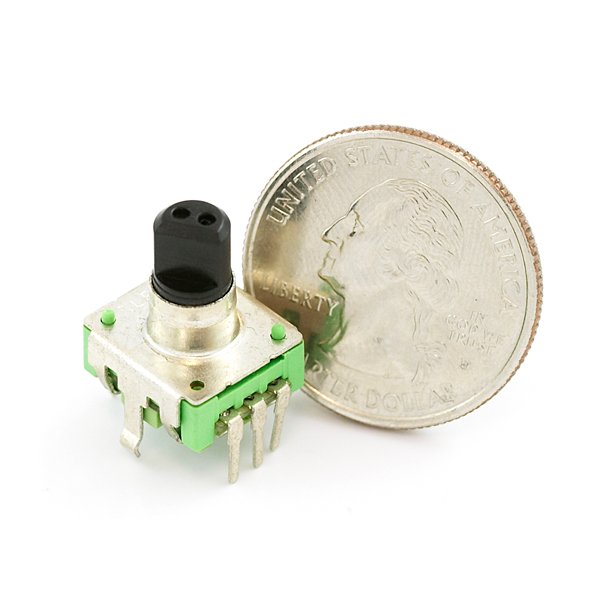
This is a 12-step rotary encoder with a nice 'clicking' feel. It's breadboard friendly, and has a pretty handy select switch (by pushing in on the knob). The encoder is different from a potentiometer in that an encoder has full rotation without limits. The unit outputs gray code so that you can tell how much and in which direction the encoder has been turned.
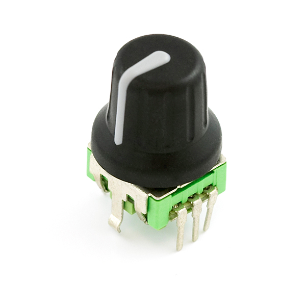
This unit does not come with a knob, but a working knob is related below.
- Bildr example showing how to use an encoder in Arduino
- Rotary Encoder Tutorial and Arduino Project
- Example Arduino Project
- Example Cooking Timer
- Datasheet
Rotary Encoder Product Help and Resources
Core Skill: Soldering
This skill defines how difficult the soldering is on a particular product. It might be a couple simple solder joints, or require special reflow tools.
Skill Level: Noob - Some basic soldering is required, but it is limited to a just a few pins, basic through-hole soldering, and couple (if any) polarized components. A basic soldering iron is all you should need.
See all skill levels
Comments
Looking for answers to technical questions?
We welcome your comments and suggestions below. However, if you are looking for solutions to technical questions please see our Technical Assistance page.
Customer Reviews
4.4 out of 5
Based on 5 ratings:
1 of 1 found this helpful:
Does the job
I got this as a general purpose rotary encoder to go in my prototyping box. The linked tutorials make it real easy to get up and running quickly. If you want to be able to add / remove this to a breadboard I'd recommend making your own breakout board for it as the pins are soft and break pretty easily. If you're just going to panel mount it then you should be good to go. I'd get/use a knob with this as the actual shaft is pretty small making it harder to grip than the sort of potentiometers you get for hobby electronics.
1 of 1 found this helpful:
Hard to panel mount
The encoder is as shown and the examples make it easy to work with. However, look carefully, this particular encoder does not have a threaded shaft. It is intended to be PCB mounted (and then standoffs on the PCB mount to the panel.) Similar units elsewhere do have a threaded shaft, so make sure to pick the one that meets your needs. The illuminated version of this encoder here at Sparkfun does have a threaded shaft.
1 of 1 found this helpful:
Works great, but confusing example code
Cheap and reliable hardware. But I found the example code pretty confusing. For somewhat more comprehensible code I recommend a look at this webpage : http://r429724.website.cvfbrtr16.service.one/rotary_encoder
1 of 1 found this helpful:
Could be better
Definitely not as breadboard friendly as you would think, Even though the spacing is correct, the pins are much wider that a standard IC pin or wire. Almost impossible to place in a breadboard. I tried a bunch. On the one I could get the pins in, it wouldn't stay secure because the pins are too short. I ended up soldering the part to a small through hole prototyping board and added some header pins.
0 of 1 found this helpful:
Well made
Rotary Encoder is well made and works well.
Hi SparkFun: I would very much like to get a good lot of these encoders. I also need knobs. I love the knob design shown on the second image of this product on this page, but I can't find a knob for sale on this site with that particular design. Is it possible to get this specific knob instead of the others you have (like Black Knob 15x19mm, etc)?
Hi, is this pin compatible with the SparkFun LED RingCoder Breakout - RGB BOB-11040 as I have them both? Thanks.
It looks like the link for Oleg's webpage results in a 404, and was moved to a new directory. I believe this may have been the orginal: https://www.circuitsathome.com/mcu/reading-rotary-encoder-on-arduino/
I have the some example code for the Arduino that does a decent job figuring out where and how much is being turned on the encoder.
Take a look here:
http://gist.github.com/154809
(if you can help improve the code please fork it)
Made it into a library:
http://github.com/medecau/QuadEncoder
this has been the most reliable method I've found so far, all other examples would slip back one step at certain speeds. Thanks very much for sharing!!
Same here. This is the only way I got the encoder to work correctly. Thanks, medecau!
Since I can't seem to find a water pressure sensor, I want to use a rotary encoder to read an analog pressure gauge. I need one that requires almost zero force to turn so that it won't impede the movement of the gauge. Would this work, or should I use a different one?
Psst - don't tell anyone I told you, but we're finalizing a water pressure sensor board. It should be on the storefront within the next month, and will be much less problematic than trying to couple a mechanical gauge to a rotary encoder or potentiometer. But I've already said too much...
Thanks. PM me if it will work up to 75psi. This will be wonderful. I've looked everywhere for one.
The max should be around 200 PSI with 24 bit resolution. But now I've really said too much. Hopefully they won't be able to track me to
The hounds are already on the way. RUN MIKE RUN!
Hmm, wouldn't that be a violation of the sparkfun dog rules??
Actually, thanks a million.
These are definitely quadrature encoders. You can multiply the counts by using edge detection. So you can increase the counts to a maximum of 48 counts easily.
But it has 12 detents. To use 48 positions you'd have to stop between detents, which is next to impossible.
That sounds great! Could you share a cade for this? I use a Wiring board.
Thanks!
hi - so i am using the 3 pins on one side to read-in the rotary data no problem. and actually there is little to no bounce, which is uncommon for such a cheap little unit! but also i have a question, i can't figure out how to read in the push button data ... it doesn't seem to be the two pins on the other side ... am i missing something?
One of the reasons for using gray code is that you don't have to worry about bounce. At a given moment in time only one of the outputs can be unstable, never both.
cuzincuz,
I've got one in front of me and the two pins are to the push button. Momentary, normally open.
Do you have any plans to offer a knob without an index mark on it? The mark makes no sense for something that's continuously rotatable.
The Silver Metal Knob you offer would have been perfect if it fit on a D-Shaft and had no mark.
I ended up pulling the knobs off my Kenwood Micro Hi-Fi (M-616DV-S), and ordered 10x spares from their parts department (part number K29-8822-08).
this no come with connections? my wife use this tool, but look no same, it no need connections, is there something same? I try and make gift for her but i no not about rotary tool
Thanks for your sharing.It is appreciated very much. And I wonder whether there are some differences between the java code 128 barcode generator ( http://www.keepautomation.com/products/java_barcode/barcodes/code_128.html ) I am testing these days and the one you mentioned above? Do you have any ideas about it? Or any good suggestion? Thanks in advance.
Just FYI, if you wire the encoder backwards (PIN 1 where PIN 2 should go and vise versa), your Arduino sketch will fail on upload saying: "avrdude: stk500_recv(): programmer is not responding."
It's a poor error message - since it doesn't point you at ALL to the actual problem.
Can this product be used as a wheel encoder? I realize it may not be designed for the durability normally required for a wheel enocder, but the most important question is if it can rotate continuously.
I have the some example code for TI Launchpad msp430 t Take a look here: https://github.com/littlepiggy/Launchpad-rotary-encoder
The code to read a rotary encoder is very very simple if you look at the pattern of bits produced. Code below. The main problem with these things is the incredible amount of switch bounce; when i spin one as quick as i can i get a quadrature event every 2 - 5 mS and bouncing out past 1mS.
While i prefer to debounce in software, in this case it's better done in hardware -- nearly all the bounce can be removed with a resistor and capacitor. 10K pullup to 5V and .1uF to ground. Don't rely on the Arduino's internal pullup.
I hate dedicating the only two interrupt pins to the encoder, so i run this code in loop() up at the top. This may not work for you -- i NEVER use delay() in my code, only millis() and a "timer" (eg. unsigned long T) and if (millis() > T) ... for timing things, so the top of my loop() comes around multiple times a millisecond for most programs.
Looking at any pair of reads (ab, bc, fg, gh, etc), adjacent bits will always be different for CW, always the same for CCW.
The core code is this:
NOTE: the website comment editor has a bug! it deletes all text following a double-less-than! which is of course the *nix input redirect. doh, it probably means this page has some serious vulnerabilities.
oh, and glue that code above below this and you have a sample program that demo's it.
I want to ultimately convert the codes to tell a audio volume control IC to step the attenuation up or down. Most such chips resolve to about 1db per step, so to have rotary encoder behave something akin to what one would expect in a volume control, I'm going to need about 128 PPR. I've been looking all week and have come to conclusion only expensive optical units with offer any PPRs > about 32. So before I start looking for an inexpensive gear arrangement, does anyone know of a a better product for me to look at?
We do have a 200ppr encoder, but in my experience you can still take a few revolutions to go from 0% to 100% and not annoy the user. Velocity-sensitivity is another option (increase by a greater gain if you're turning it faster).
A good knob for this is mouser part 450-4761
There is no Eagle file for this part in the SparkFun Eagle library! :(
I'm having trouble. So If I use the example from : http://www.circuitsathome.com/mcu/programming/reading-rotary-encoder-on-arduino
All I'm getting is 0,1 and 0,1 whenever I turn the encoder left or right. The code should increment the counter. Any thoughts?
I ordered a few of these inexpensive rotary encoders to play with and electrically they work fine. I have some simple PIC test code to inc/dec a 7-segment LED and seems pretty reliable. What I don't like about this part is the action... it's too easy to get stuck in the middle of the 12 indents, especially when turning slow. I'm assuming a higher quality part would do a better job of only stopping on the 12 position indent and not in the middle of two positions.
Looking at the data sheet this has quadrature outputs and not gray code. There is a big difference. Sparkfun can you comment on this and / or change the description.
-Sam K
No difference: a 2-bit Gray code is quadrature code.
"It's breadboard friendly,"
Not really. DO NOT PUT THIS IN YOUR BREADBOARD!!!! It bends the leads and then they snap off. You have two options:
baum
Worth Noting that these are 48 steps/Revolution not 12, there are 12 DETENTS, each detent counts as 4 steps electrically.
The number of steps is equal to the number of pulses per channel per revolution, not the number of edges on both channels (which indeed would be 4 times as many).
This is true, and it allows code to be a lot shorter than other people have it. If it is being used by each click at a time, then connecting the common to 5v and the other to 2 input pins(with some pull-down resistors), you can see which way it was turned by seeing which pin goes high first(it will be all messed up if you keep it in a position between clicks, however).
it depends on how you're reading the code. they are 12 steps per revolution. you're code is just outputting 4 signals per step. try some of the other example codes.
I found the example code pretty confusing. For more understandable, no library and rock steady decoding check out this page.
Thank you, thank you, thank you!!! The best code ever when it comes to this problem - I agree.
Thank you! This is by far the best working code I've found for this encoder.
I have created a library that works with this encoder. See it here:
http://code.google.com/p/adaencoder
It differs from most other code by being interrupt-driven and easy to use on any pair of Arduino pins (with caveats that the pins must share an ATmega PORT [see the source code for more info]).
Enjoy!
I have designed my own simple rotary encoder breakout board for this part out of necessity. You can check it out here: http://www.inmojo.com/store/disassemble-reassemble/item/rotary-encoder-breakout-pcb-only/
First, I can’t believe that someone does not make an I2C decoder for an Rotary Encoder. YES, I have ran across people making PICs that can do it, but I am still surprised that no one has made a 12 pin chip that can fit the bill.
What I did find, that I thought was interesting, was a made from two 74HC132 chips with some passive glue >> http://archive.electronicdesign.com/files/29/21422/fig_02.gif Full article is here >> http://electronicdesign.com/article/analog-and-mixed-signal/simple-quadrature-decoder-suits-rotary-encoders214.aspx.
What caught my eye was that there were only two outputs: INC, and DIR.
My frustration with tying a rotary encoder to an Arduino is that you’re wasting resources of the Arduino. Also you have to make sure whatever code you are writing never hangs so to prevent the Arduino from seeing a INT or changed state from the Rotary Encoder. Yes, I do realize that most Arduino are fast. But there always some type of code that takes it’s sweet time to get through that prevents the processor from seeing the INT or a changed state.
I see this exactly the other way around. I like to use the Arduino for this and do everything in software (which I can change if I find out it does not work), instead of using 10 external components and a custom PCB. If you look at the code - it takes only a few lines. Also, you would not free up any pins Enc A and Enc B with one solution and INC and DIR with the other. I guess it comes down to preference and what you are more comfortable hardware vs software...
I agree with your assessment with INC and DIR. But what would really be cool is if the Rotary Encoder could be hooked up to something like a PCA9555 {http://www.nxp.com/documents/data_sheet/PCA9555.pdf } and let the PCA9555 do the monitoring of the Rotary Encoder- no software for monitoring the Rotary Encoder, just software that talks I2C, and responds to a INT. Then all you have is two wires for I2C, and an INT. Everything is addressable.
I think the next step for the Mayhew Labs Rotary Encoder LED Ring Breakout Board is to add RGB LEDs, and Maybe three PCA9635 chips that does all the mixing/dimming on the chips for the LEDs (NO-resistor networks), again all I2C bus (-two wires and the INT, plus VCC and Vss). And all the PCA9xxx chips are addressable meaning you can have a number of I2C chips on the same I2C buss. The PCA96xx can run around 1MHZ and the PCA9555 runs around 400 KHZ. That means the I2C bus has to run at the lower speed unless you can MUX it so they see the speed they like. I just like the thought that you could have the color you want, at the brightness you want, and it does not mean that your locked into one set of colors. HECK you could have the UV meter style output, or maybe one color where everybody else is another color. If the PCA9555 cant trap and help with decoding, then I guess we are stuck with having the Arduino do it.
For whoever may find it useful: I used a bunch of these rotary encoders for a prototyping project and I wrote a simple wrapper library around them.
You can find the code on GitHub:
https://github.com/micheljansen/arduino-rotary-knob
#define PIN_OFFSET 22
#define NUMKNOBS 6
Knob knobs[NUMKNOBS];
void setup()
{
for(int i = 0; i < NUMKNOBS; i++) {
knobs[i].setup(PIN_OFFSET + 2i, PIN_OFFSET + 2i + 1);
// abuse output pins for gnd
pinMode(i+2, OUTPUT);
digitalWrite(i+2, LOW);
}
Serial.begin(9600);
}
void loop()
{
for(int i = 0; i < NUMKNOBS; i++) {
int dir = knobs[i].read();
if(dir) {
if(dir > 0) {
Serial.println("right");
}
else {
Serial.println("left");
}
}
}
}
Does anybody know of a knob that fits this? I tried the silver metal knob (COM-10001) and it definitely does not fit - the shaft is too big. I tried a knob off another piece of equipment (perhaps similar to the black knob, COM-09998) and it didn't fit either. It's pictured with COM-08828, is that the only one that fits?
Thanks.
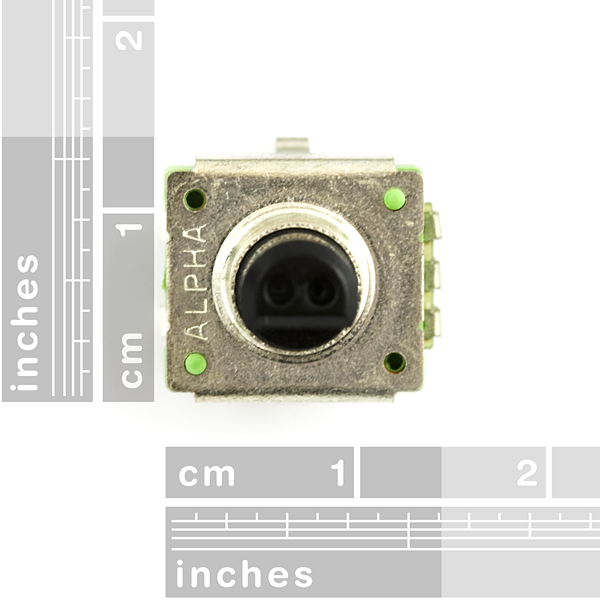
Saccade, if you check the data sheet, you will see that this has a 6mm shaft as opposed to the more common (in the US) 1/4" shaft. You can find many knobs on the web for a 6mm shaft - Google "6mm shaft knob" for a zillion of them. The biggest problem you'll have is finding one that doesn't cost as much as two of these encoders! You can sometimes make a 1/4" inch knob fit very nicely by shimming with a split ring made from an aluminum soda can.
Thanks; actually I just didn't push hard enough. Once I got the encoder mounted, I was able to Push Pretty Hard on the COM-10001 silver knob, and it did fit on the encoder's shaft.
I can't recommend this. I tried it and the encoder broke under the pressure. If you have your heart set on the 10001 knob, you'll want to drill out the knob a bit more and use some glue.
Update: I drilled my 10001 knob out at 15/64ths inch, and now it press-fits great on the shaft of the (replacement) encoder. I probably won't even glue it.
Here's a slick, 2-wire interrupt-driven Arduino solution (which should be easily adaptable elsewhere) that I saw over at Ayars' Hardware Hacks. It only determines direction, but that's all I'm going to be using this for.
Here's the Arduino code I ended up using.
I agree with fluidic on the feel of this encoder. it is very weak, and unstable. but for 3 bucks, it is a great deal for proto work. if you need anything with single-click precision, this model won't work very well. I used Oleg's code and it ran first build, as advertised.
Tactile feedback is kind of weak, more bumpy than snappy. Still noticeable though. Good enough for prototyping. Might want to try a wider range of alternatives if you're considering deployment or building something permanent.
any tips on using this with COM-10001? I ordered two of each and, alas, the knob doesn't really fit. I am loath to use glue but I suppose I will if I must.
Otherwise MANY thanks to all the helpful links! with the info here I got it up and running in about as much time as it took to open the box. =-D
I am using this with COM-08828 and had problems with the button sliding down the shaft so far that the select switch would not work. I solved the problem by putting a small wad of paper in the knob so that it could not slide all the way down, but is still secure on the shaft. <br />
<br />
BTW, I am using this with a parallax propeller and it works nicely with the article/code from Jon William for Nuts and Volts Magazine:<br />
<br />
Article:<br />
http://www.parallax.com/Portals/0/Downloads/docs/cols/nv/prop/col/nvp6.pdf<br />
<br />
Code:<br />
http://www.parallax.com/Portals/0/Downloads/docs/cols/nv/prop/code/nvp6.zip
It works best with knobs that have set screws.
A word of warning about using these in an enclosure. There is very little room between the bottom of the knob (sold seperately) and the encoder case. Without pressing the "button" there is 1.0mm (assuming you make holes for the two small bumps on top of the encoder case). With the button pressed you're down to about 0.5mm (I couldn't get my calipers in between to measure).
I ended up cutting holes in my enclosure large enough for the knobs to fit inside. My case would have looked cleaner if I could have had holes just big enough for the shafts.
Very easy to use. I have written some introduction on how to do so here: http://bit.ly/cNdzV7
Be warned! This one only has 12 steps per cycle instead of the usual 20.
It's clearly said in the description. Also there is no "usual". All number of steps exist: 12, 15, 16, 20, 24,...
Anyone have an eagle part for this?
See my cooking timer example (link above) - it has a verified eagle part for download.
Yeah, just verified the footprint. I'll upload it as soon as I test the board.
Uploaded the footprint, etc, to http://www.ste-marie.net/RotaryEncoder.lbr
I have the push working nicely.
But cannot make sense of the rotary encoding. The values the device reports seem very arbitrary. It is frustrating; I am going to need to re-think the interface to this project. If I had been able to make this work as expected it would have been a perfect choice for this control interface.
For each click of the encoder shaft you get momentary connection on both encoder outputs. then they go back to open circuit. The timing of the connections tells you which way the shaft was turned.
Take a look at this, it may be relevant to your interests: http://en.wikipedia.org/wiki/Rotary_encoder#Incremental_rotary_encoder
Yes, I agree with skelso that quadrature would have been more descriptive. The datasheet also does not fully describe which pins the push switch connects to, but I assume that they are the two unlabeled pins. I also assume that they meant to describe the switch as a momentary, normally open type which goes to closed when the shaft is pressed down.
Clarity in datasheets is becoming rare nowadays...
Wouldn't most say this is a quadrature encoder? Gray code implies absolute, and this would need four bits of Gray to be that. Yes, quadrature is a two-bit Gray code, but still...
"Gray Code" is a sequence of binary numbers where only one bit can ever be in transition at any given time. People use it for absolute positioning, yes. They also use it for quadrature encoders like this one.
I think they key idea of gray code is that only one bit changes between adjacent states so there is less guessing about the state during a transition. <br />
<br />
This is true of a quadrature encoding, as you said.
The Rotary Encoder sku: COM-09117 is missing its PDF data sheet. http://www.sparkfun.com/datasheets/Components/TW-700198.pdf fails.
:( Mine came with a pin broken and I have contacted sparkfun,but I was really hoping i could get this project done :(
You REALLY need to "pad" the boxes you use...