- Home
- Product Categories
- 5mm
- LED - RGB Diffused Common Cathode

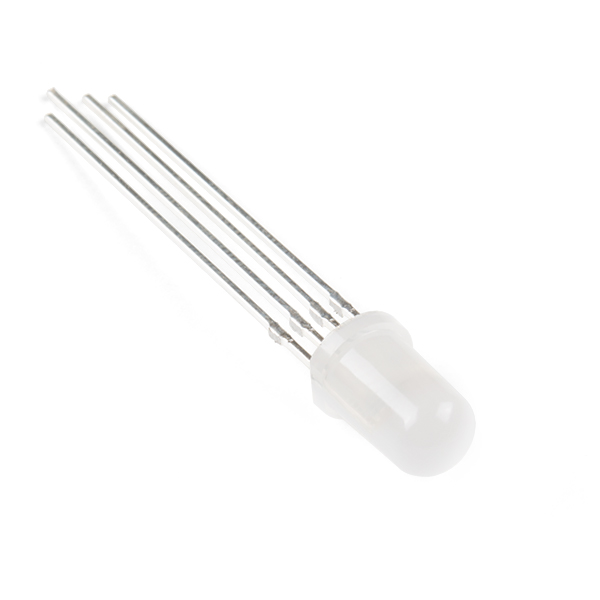
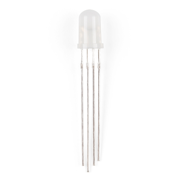
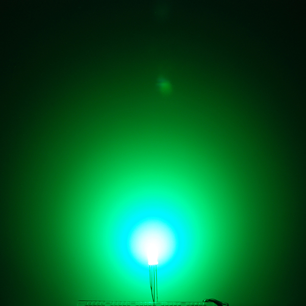
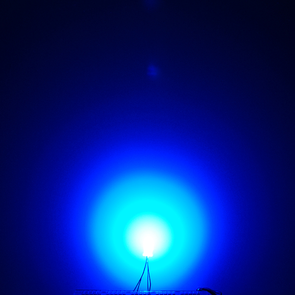
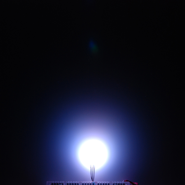
Ever hear of a thing called RGB? Red, Green, Blue? How about an RGB LED? These 5mm units have four pins - Cathode is the longest pin. One for each color and a common cathode. Use this one LED for three status indicators or pulse width modulate all three and get mixed colors!
These LEDs are diffused; so they'll appear dimmer, but have a wider viewing angle.
- Forward Voltage (RGB): (2.0, 3.2, 3.2)V
- Max Forward Current (RGB): (20, 20, 20)mA
- Max Luminosity (RGB): (2800, 6500, 1200)mcd
LED - RGB Diffused Common Cathode Product Help and Resources
Wireless Glove Controller
April 24, 2019
Build a wireless glove controller with Arduinos to trigger an LED using XBees!
Wireless Gesture Controlled Robot
April 25, 2019
Control the RedBot wirelessly based on the movement of your hand using an accelerometer, Arduino, and XBees!
SparkFun Inventor's Kit Experiment Guide - v4.0
November 15, 2017
The SparkFun Inventor's Kit (SIK) Experiment Guide contains all of the information needed to build all five projects, encompassing 16 circuits, in the latest version of the kit, v4.0a.
SparkFun Inventor's Kit Experiment Guide - v4.1
August 8, 2019
The SparkFun Inventor's Kit (SIK) Experiment Guide contains all of the information needed to build all five projects, encompassing 16 circuits, in the latest version of the kit, v4.1.2 and v4.1.
Non-Addressable RGB LED Strip Hookup Guide
February 19, 2020
Add color to your projects with non-addressable LED strips! These are perfect if you want to control and power the entire strip with one color for your props, car, fish tank, room, wall, or perhaps under cabinet lighting in your home.
1 of 1 found this helpful:
Color Mixing
I recently had a customer contact us about the illumination profile of the LED. These are the resistor values he recommended for an even illumination across the RGB colors.
"I used a Texas Instruments OPT3001 to accurately measure the output as would be perceived by the human eye and used this information to create more appropriate resistors values: red: Lux=61.26; actual resistor value = 217 Ohms; Nominal resistor value = 220 Ohms green: Lux=55.24; actual resistor value = 4640 Ohms; Nominal resistor value = 4700 Ohms blue: Lux=53.34; actual resistor value = 2273 Ohms; Nominal resistor value = 2200 Ohms."
Core Skill: Electrical Prototyping
If it requires power, you need to know how much, what all the pins do, and how to hook it up. You may need to reference datasheets, schematics, and know the ins and outs of electronics.
Skill Level: Competent - You will be required to reference a datasheet or schematic to know how to use a component. Your knowledge of a datasheet will only require basic features like power requirements, pinouts, or communications type. Also, you may need a power supply that?s greater than 12V or more than 1A worth of current.
See all skill levels
Comments
Looking for answers to technical questions?
We welcome your comments and suggestions below. However, if you are looking for solutions to technical questions please see our Technical Assistance page.
Customer Reviews
4.5 out of 5
Based on 2 ratings:
1 of 1 found this helpful:
Best customer service!
I had ordered these as part of a class order for one group. There was a miss count on the item, but customer service got me that part the next day and was so, so pleasant to deal with.
Check out what this guy did with these things!!!
http://www.instructables.com/id/Aurora-9-bar-The-Essence-of-Aurora/
It's amazing!
Does anybody know where I can get diffused rgb led's for cheap if I need to get mass quantities.
If you want reasonably reputable suppliers, stick to the main electronics suppliers: digikey, jameco*, newark/farnell/element14, mouser, followed by the slightly more consumer-oriented: all electronics*, electronics goldmine* and futurlec*.
If you're willing to take a bit more of a gamble, try amazon.
If you just want lowest possible cost and don't really care about the quality (not saying they're all bad), there's: e-bay, aliexpress, dx*.
Note that not all of them will have 5mm diffuse RGB LEDs (* those with an asterisk I couldn't find any real quick, but that might just require better filtering/searching), and others will include non-diffuse results in their filters/searches, and you'd have to make triple-sure you're getting the right kind (common anode vs common cathode, no flashing/'color change' ones, etc.)
If you need thousands upon thousands of them, try talking to a manufacturer directly :)
Eagle is complaining of overlap between each solder point, and the autorouter won't work on the footprint. Is there something I can change within eagle to force it?
There's a value called "restring" in the DRC that specifies the minimum pad size. If the pad is smaller in the library, EAGLE will enlarge it to the restring size, which causes shorting problems as you've found. To fix it, go into the DRC dialog and change the restring value to a smaller number (0 is OK); the design will then use the proper size specified in the library.
Nevermind. It looks like I forgot to set the grid size to 6 instead of 50 on the autorouter.
Using Eagle's own autorouter? Wow! Unless you really prefer SM, better use http://freerouting.net/ one. Needs some re-learning but works 10x better.
I have changed the restring pad sizes to 0 (for all max, percent and min) and the overlap error goes away, but when I try to use the auto-router, everything but the led routes. The yellow ratsnest is left for those 4 pins. Any idea what I might be doing wrong?
Great! Thank you very much!
The SparkFun Library has now been updated as of 2/2/2013 for this through hole tricolor LED. You can find it under “LED-RGB-THRU” or “LED-RGB-CC-THRU” depending on the package under SparkFun-LED.lbr. If you are using the common anode you can find it under “LED-RGB-CA-THRU.”
To download the latest libraries just go to Github => https://github.com/sparkfun/SparkFun-Eagle-Libraries
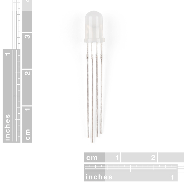
The pin spacing is 0.80 mm from eachother and the pins are 0.50 mm x 0.50 mm thick.
Common anode would be great because they play nice with the TLC5940.
Any common anode varieties? I find common-cathode is a hassle to work unless you're hooking straight to 5V logic pins — it's way easier to work with the common cathode NPN / common drain N-FET outputs on shift registers like http://www.sparkfun.com/products/734 , "Shift Register 8-Bit High-Power - TPIC6B595".
anyone know how these compare in brightness to the clear RGB leds? the max luminosity on these is much higher (2800, 6500, 1200 vs 800, 4000, 900) which seems counterintuitive.
they sell these at radioshack for $3 each. get yourself the 25pc, or 100pc packs and they will be < $1 each.
can't beat the price for this good of rgb LED (others aren't as good)
Its so weird, Ive got a Teensy running Arduino code, with this LED, and yet I only can run Red and Blue on the Analog pins, while Green only will run on the Digital pins. When I try to put all of them on analog or all on digital, they either dont work, or the output is very dim. Anyone have any suggestions on this?<br />
<br />
By the way Ive gotten all 3 to show pretty bright, so I dont know if thats a factor or not. Using 1k Ohm resistors is too much to get any output, but thats what Ive been using with regular LEDs.
Oops, I just realized my problem is that I wasnt using PWM pins like I was supposed to. It all works now. ;)
you guys should order some of those rgb leds that have the 4 legs bent apart so that there bread board and potoboard friendly.
They are currently just breadboard acquaintances, it is up to you to make them be friendly - it's half the fun.
The "Wiring Example" link http://wiring.org.co/learning/basics/rgbled.html on this page contains a known attack/intrusion attempt as detected by Norton 05 Aug 10 using "HTTP Phoenix Toolkit Java Class Activity"
5mm T1-3/4 RGB LED's are 4-pin with 0.05" spacing, for square 0.028" pins (x1.414) use a 0.040" hole size
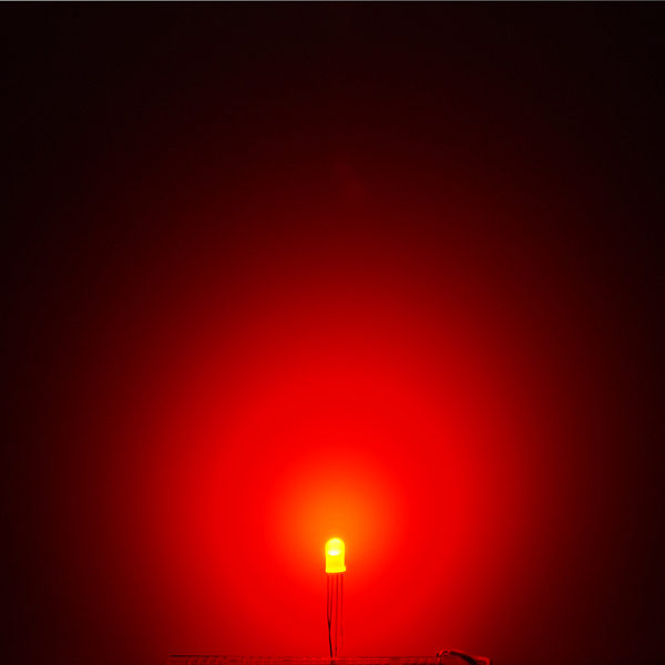
I really like this LED. I wish I would've ordered more! The only problem with it is that the red LED has a lower rated voltage and thus a lower resistance than the green and blue. If you want to only use one resistor (connecting the negative lead to ground) you must add software limits on the red because it will "drown out" the blue and green. Electricity flows to the path of least resistance, the red LED has the least resistance and will cause unexpected issues with a common resistor. I haven't tried it yet but I think 3 individual source resistors would fix this. As for the colors, they are awesome, using PWM signals you can make any color you want. I wrote a program that generates random colors every second, it's kind of a cool thing to leave running and add some color to a dull white dorm room.
Actually, if my understanding of diodes is right, the red LED will cause a lower voltage drop, it has nothing to do with resistance. If this is the case, running one resistor to ground will cause a bit of a mess here. This means all 3 LEDs are directly in parallel, and since voltage drop must be equal in parallel, but the rated voltage drops for the LEDs are different, this is going to do some weird stuff. Adding resistors in series with each LED will fix this because the voltage drop over the resistor connected to the red LED will just be a little higher.
Remember to adjust the resistors so that each LED gets equal current, too. If you put the same value on all three, the red will still dominate.
a 330 ohm on red and a 220/240 ohm on green and blue seem to give me the best color
I can imagine these appear dimmer than the clear lenses LEDs but their Luminous Intensity is much higher than the clear.
Has anyone used these with the 4x4 button pad break out's? are they just too dim?
I probabyly I don't need the diffusing characteristics because the silicone buttons would take care of the diffusion but the clear lenses LEDs are out of stock. And, $1.95 is a good price for RGB LEDs, they're more than 2X expensive at digikey.
I actually prefer using the diffused LEDs with the button pads. I tried both, and I've found that you can't tell a difference in brightness, but you can see the shape of the clear LEDs through the buttons.
Unfortunately I ordered four and let the smoke out of one of them. Although I already have four clear, I might spend the extra money to get 4 diffused in my buttons.
Fantastic! I hope the diffusion helps to counter the offset of the colored diodes. With the other RGB LED, I had to use a small piece of paper to help blend the colors.