Button Pad 2x2 - Breakout PCB
COM-09277
Button Pad 2x2 - Breakout PCB
SKU: COM-09277
$7.25
In stock
SKU
COM-09277
Product Overview
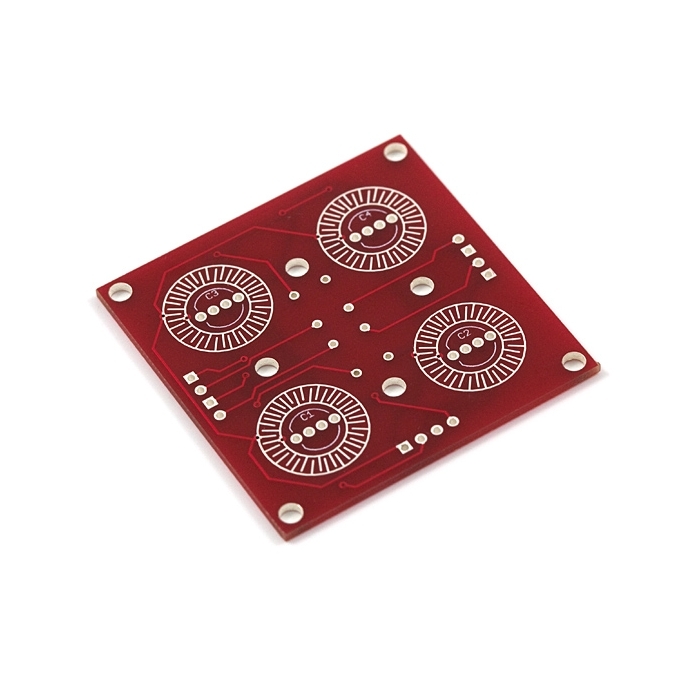
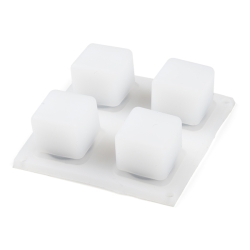
This a simple breakout board for the button pads. Each LED and button is brought out to the side connectors. The connectors are soldered to the back side of the PCB. We recommend trimming the connector leads on the button side as short as possible to reduce the deflection of the pad.
Now with footprints for diodes! Use the super cheap 1N4148 through-hole diodes. These can be used to isolate the switches to make for a bit easier decoding.
Documents:
Similar Items


Hookup Accessories
-
-
-
-
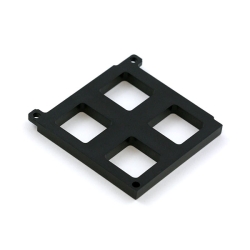 Button Pad 2x2 Bottom Bezel
Special Price Current price: $0.95 Regular Price Original price: $4.50Out of stock
Button Pad 2x2 Bottom Bezel
Special Price Current price: $0.95 Regular Price Original price: $4.50Out of stock -
-
-
-
-
-
-


Documentation
Customer Reviews

Button Pad 2x2 - Breakout PCB
$7.25
COM-09277
Stock and Customer Discounts
$7.25 retail price.
Available Discounts
- $6.89 | 10+ units
- $6.53 | 25+ units
- $6.16 | 100+ units