
Face Tracking with a Pan/Tilt Servo Bracket
Overview
In this tutorial we're going to look at how to use OpenCV, a real time computer vision library, with Processing, Arduino, a webcam and a pan/tilt bracket to create a video that will keep a persons face in the middle of the frame as they walk around the room. A video of the final product illustrates the concept a little better than I can explain it.
Software Required
- Arduino
- Processing
- OpenCV Framework (Windows, Mac, Linux)
- OpenCV Processing Library
Firmware Required
Hardware Required
- Arduino Uno (or other 5V Arduino Compatible board)
- Pan/Tilt Servo Bracket
- Webcam
- USB Cable
- 9V DC Power Adapter for Arduino
- Breadboard
- Jumper Wires
- Male Header Pins (2x 3 pin lengths)
Assembly Guide
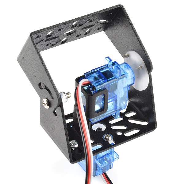
There are several pieces for this project that need to be assembled. Start by putting the Pan/Tilt Bracket together using the assembly guide from the product page. This will show you how to put the bracket together and install the servos for controlling the bracket's orientation.
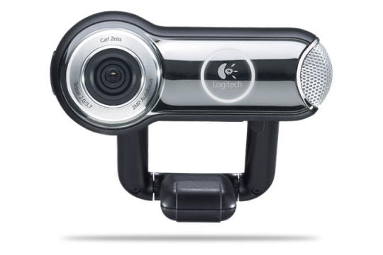
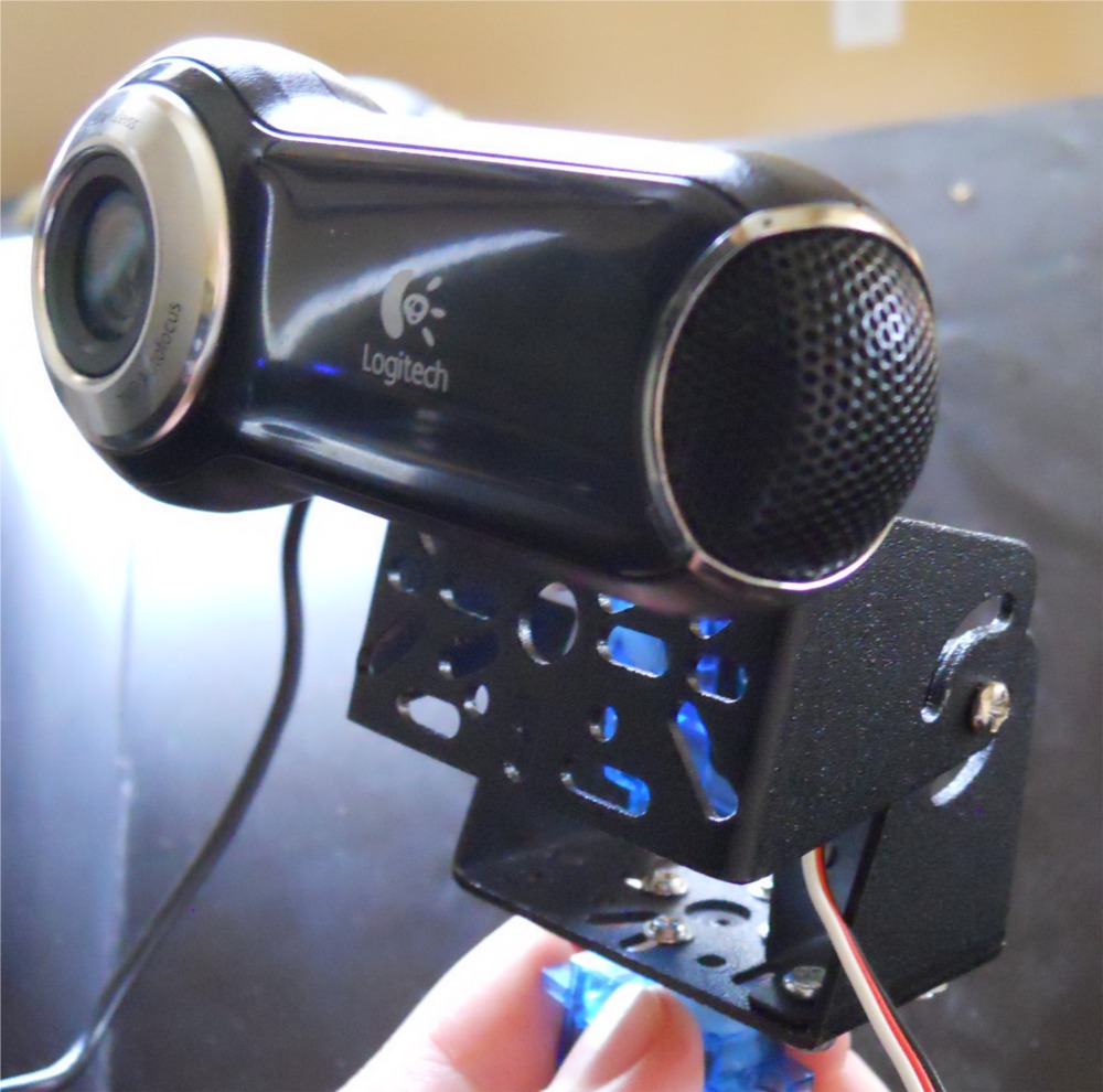
Once the Pan/Tilt Bracket has been assembled we need to find a way to mount the webcam onto the bracket. I'm using a Logitech Webcam that we lying around the office. It came on this little mounting swivel so that you can hang it from the top of a monitor.
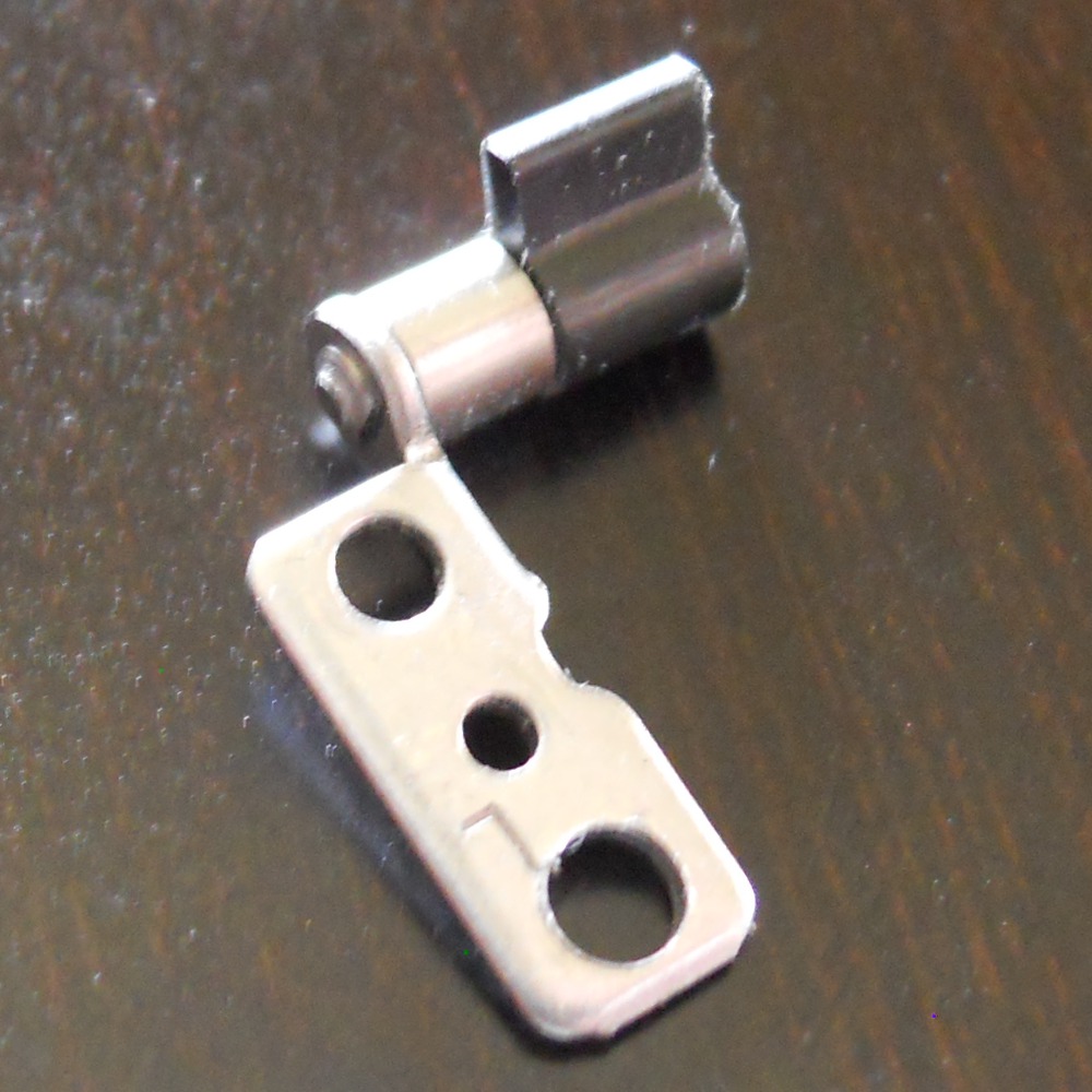
I figured that the camera had to be mounted onto it's bracket somehow, so if I could take it out of the current bracket it might make it easier to mount to the pan/tilt bracket. After taking out a handful of screws, and pulling apart some rather reluctant plastic, I was lucky to find that there were some small metal swivels that I could mount the camera with.
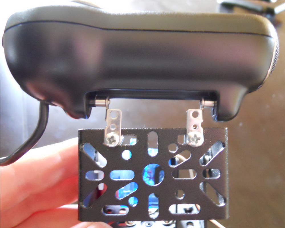
The only thing left was to figure out how to mount the swivels onto the bracket in a fashion that would allow the camera to be put back onto the swivels. Since there are a ton of cut-outs in the pan/tilt bracket it wasn't too difficult. I found some small screws to mount the swivel to the bracket. Unfortunately the screws were just a tad too big to fit through the holes in the swivel, so I enlarged them a bit with a drill press. After making the holes bigger I just mounted both swivels to one edge of the bracket, and then with a little bit of wiggling I got the webcam back onto the swivels.
If you don't have the same webcam you'll have to find your own way to mount the webcam to the pan/tilt bracket. Don't be afraid of a little Duct Tape! One thing to check before mounting the camera to the bracket, though, is the range of motion of the pan/tilt. I wanted the camera to have the widest range of motion possible when tracking, so I found the mid-point of the pan and tilt angles, and then mounted my camera so that the lens was facing forward. To find the mid-point of the pan/tilt range of motion just manually move the bracket from side to side, and up and down and approximate the center position for each axis.
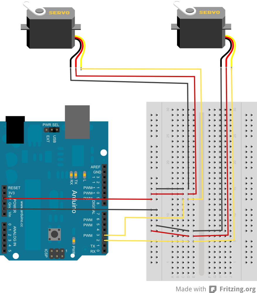
Now that the camera jig is set up we need to assemble the electronics. Since the Arduino is capable of providing enough power for two servos, there's not much to the assemble. All we need is an Arduino, a breadboard, a couple 3 pin Male Header strips, and some wire. The fritzing diagram below illustrates how to connect the entire setup. Just try to make sure that you plug the wire for the pan servo (left and right movement) into pin 2 of Arduino, and plug the wire for the tilt servo (up and down movement) into pin 3.
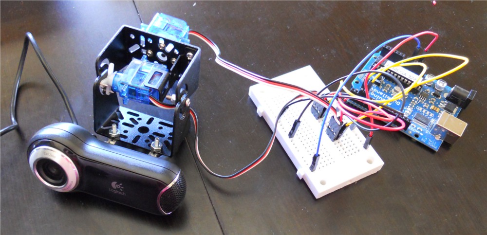
Everything should now be assembled and ready to go. Things are a bit messy, but they'll work.
Installing the software
Before we can get started with the code for this project there are a couple of software programs that need to be installed. First and foremost, if you don't have Arduino installed you'll need to go get it. There are great instructions for installing the software on any OS right on the Arduino download page. You also need to install Processing, which is very similar to Arduino, but made for writing programs for a computer (like, a real computer) rather than for Arduino. Processing also has great installation instructions for every operating system.
The brains of this project, though, come from OpenCV. OpenCV (Open Computer Vision) is a library for real-time image processing. It actually allows you to do all sorts of cool things, but we're going to use it for detecting faces. If you read the OpenCV webpage you'll notice that the only things that are really supported are C, C++ and Python. However a quick google for "OpenCV Processing" found a project from a group that has created an OpenCV library for Processing and Java.
In order to use OpenCV with Processing we'll need to install the OpenCV Framework and the OpenCV Processing Library. We'll also download the OpenCV Processing Examples so we can get a head start on writing the code. The OpenCV for Processing and Java site has good instructions on how to get these things installed. I copied these instructions from them.
Start by installing the OpenCV Framework to your computer. If you're using Windows, download the installer from the sourceforge page for the project. Make sure you download OpenCV_1.0.exe, not the zip file. And yes, there are newer version of the OpenCV Framework, but they don't work with OpenCV for Processing, so make sure to download version 1.0. When you run the installer, make sure you agree to have the OpenCV directory added to your system path. You'll need to reboot after installing in order for the system changes to take affect. If you're using a Mac, just download the OpenCV image and follow the installer instructions. Finally, if you're a Linux user, download/compile/install the source files for OpenCV.
Once the OpenCV framework is installed, the OpenCV Processing library still needs to be installed in order to use OpenCV from Processing. Just download the OpenCV Processing Library and move it to your Processing libraries folder. The libraries folder resides inside the Processing sketchbook folder. You can find the sketchbook folder by opening Processing, then going to File->Preferences. Make sure to extract the OpenCV library folder into the libraries folder, don't just put the zip file into the folder.
Finally the OpenCV Processing examples need to be downloaded. Either create a folder inside the OpenCV Library folder called 'examples' or just put the examples into the Processing sketchbook. Again, make sure the zip file is unzipped into one of these folders.
Once the OpenCV Processing examples are installed, and Arduino, Processing, OpenCV Framework and the OpenCV Processing library have all been installed, we've got everything we need to finish the project.
Writing the Code
By now you've got the Pan/Tilt Bracket with a Webcam mounted onto it, and all of the required software has been installed. If you watched the video at the beginning of the tutorial you should have a general understanding of what this project will do. Basically the servos are going to move the webcam and keep the subjects face in the center of the video feed. Pragmatically speaking, Processing takes the video input from the webcam and uses the OpenCV library to analyze the video. If a face is detected in the video, the OpenCV library will give the Processing sketch the coordinates of the face. The processing sketch will determine where the face is located in the frame, relative to the center of the frame, and send this data through a serial connection to an Arduino. The Arduino will use the data from the Processing sketch to move the servos connected to the Pan/Tilt bracket. Let's start by taking a look at the Arduino sketch, which is called SerialServoControl.
Arduino Sketch: Serial Servo Control
If you haven't already grabbed the Arduino firmware for this project, go ahead and download the SerialServoControl sketch and save it to your sketchbook. Once you've downloaded it, open the sketch in Arduino, start by reading the comment section at the top. Basically this sketch will analyze a serial input for commands and set the servo positions accordingly. The command structure for the serial commands is simple. A command consists of two bytes: a servo ID and a servo position. If the Arduino receives a servo ID, then it waits for another serial byte and then assigns the received position value to the servo identified by the servo ID.
        #include <Servo.h>  //Used to control the Pan/Tilt Servos

//These are variables that hold the servo IDs.
char tiltChannel=0, panChannel=1;

//These are the objects for each servo.
Servo servoTilt, servoPan;

//This is a character that will hold data from the Serial port.
char serialChar=0;

void setup(){
  servoTilt.attach(2);  //The Tilt servo is attached to pin 2.
  servoPan.attach(3);   //The Pan servo is attached to pin 3.
  servoTilt.write(90);  //Initially put the servos both
  servoPan.write(90);      //at 90 degress.

  Serial.begin(57600);  //Set up a serial connection for 57600 bps.
}
The Arduino Servo library is used to easily control the pan and tilt servos. There aren't that many variables; a couple are used to keep track of the servo ID values for each servo, and then an object (or instance) is created for each servo. Finally there's a character variable that will be used to keep track of the characters that come in on the Serial port.
In the setup section, we tell the Arduino which pins have the servos attached to them. In this case, we're telling the Arduino that the tilt servo is attached to pin 2 and the pan servo is attached to pin 3. Make sure that this reflects how the hardware is actually connected in your setup. If you get it wrong, it's easy to fix. Just relocate the wires. After telling the Arduino where the servos are connected, we set the initial position of the servos to be 90 degrees; this is just so that the setup goes back to a good starting point every time the Arduino powers up. Finally, in order to use the serial port we set up the connection with the Serial.begin command; this sketch will be using a 57600bps baud rate.
        void loop(){
  while(Serial.available() <=0);  //Wait for a character on the serial port.
  serialChar = Serial.read();     //Copy the character from the serial port to the variable
  if(serialChar == tiltChannel){  //Check to see if the character is the servo ID for the tilt servo
    while(Serial.available() <=0);  //Wait for the second command byte from the serial port.
    servoTilt.write(Serial.read());  //Set the tilt servo position to the value of the second command byte received on the serial port
  }
  else if(serialChar == panChannel){ //Check to see if the initial serial character was the servo ID for the pan servo.
    while(Serial.available() <= 0);  //Wait for the second command byte from the serial port.
    servoPan.write(Serial.read());   //Set the pan servo position to the value of the second command byte received from the serial port.
  }
  //If the character is not the pan or tilt servo ID, it is ignored.
}
The loop section of the SerialServoControl sketch is also pretty short. Basically we wait for a character to come in on the serial port, and we only act if the character is an ID for one of the servos. Because of the command structure, the next byte to come from the serial port should be the servo position for the previously sent servo ID. So the sketch waits for another character from the serial port, and when it arrives the servo position is updated to the value read from the serial port. Simple!
Processing Sketch: Face Detection Example
The OpenCV framework is very powerful, and powerful frameworks tend to be a bit intimidating to work with. Luckily the OpenCV Processing Library comes with couple example sketches showing us how to work with the library. Make sure you have the OpenCV Processing Library installed, as well as the OpenCV Processing Examples. Open the example named "face_detection." When I was first exploring the examples I didn't know what "face_detection" actually did, but it sounded promising.
Make sure you have a webcam plugged in before running the sketch. Once your webcam is plugged in go ahead and run the sketch. What happens? You should see just a streaming video from the webcam. Nothing special. Bummer. But wait! If you check out the program output in the processing window, the top line has an error message. The error message reads "The haar classifier cascade file 'haarcascade_frontalface_alt.xml' can not be found in folders, you must specify the full path instead." Ok, so I don't know what a haar classifier cascade is, but I do know that this error message is indicating that the sketch folder is missing a file. To correct this error, you need to find the 'haarcascade_frontalface_alt.xml' file in the OpenCV Framework directory. The file should be in '.../OpenCV/data/haarcascades.' Just copy the XML file named 'haarcascade_frontalface_alt.xml' and paste it into the "face_detection" sketch folder in your Processing Sketchbook libraries folder.
Go back to Processing and run the sketch again (close the sketch if it's still open). Now, if you're face is in the webcam's field of view, you should see a colored rectangle outlining your face. Awesome! You might also notice that if you click and drag inside the window the brightness and contrast will change. Let's check out the code to see what information we can get that might help us control a servo. Keep in mind, I'm no expert on OpenCV, so we're learning this together.
        import hypermedia.video.*;
import java.awt.Rectangle;

OpenCV opencv;

// contrast/brightness values
int contrast_value    = 0;
int brightness_value  = 0;

void setup() {

    size( 320, 240 );

    opencv = new OpenCV( this );
    opencv.capture( width, height );                   // open video stream
    opencv.cascade( OpenCV.CASCADE_FRONTALFACE_ALT );  // load detection description, here-> front face detection : "haarcascade_frontalface_alt.xml"

    // print usage
    println( "Drag mouse on X-axis inside this sketch window to change contrast" );
    println( "Drag mouse on Y-axis inside this sketch window to change brightness" );

}
In the initialization and setup sections there doesn't seem to be anything too complex going on. In the initialization section a couple of libraries are included, and a couple of variables are declared. Then in the setup section, a window is created, and the opencv instance is configured. Basically after the instance of the OpenCV class is created, the class is configured to capture a video that same width and height of our window, and the detection shape is set to detect the image defined by the CASCADE_FRONTALFACE_ALT file. (Try out some of the different haarcascade xml files to see what they do! Just copy the XML files like you did before, and rename the file in this line of the sketch). After configuring the openCV instance, some instructions are printed to the user on how to manipulate the brightness and contrast.
        void draw() {
    // grab a new frame
    // and convert to gray
    opencv.read();
    opencv.convert( GRAY );
    opencv.contrast( contrast_value );
    opencv.brightness( brightness_value );

    // proceed detection
    Rectangle[] faces = opencv.detect( 1.2, 2, OpenCV.HAAR_DO_CANNY_PRUNING, 40, 40 );

    // display the image
    image( opencv.image(), 0, 0 );

    // draw face area(s)
    noFill();
    stroke(255,0,0);
    for( int i=0; i<faces.length; i++ ) {
      rect( faces[i].x, faces[i].y, faces[i].width, faces[i].height );
    }
}

</faces.
This part of the sketch is surprisingly short! The OpenCV instance reads a frame from the Webcam, converts it to grayscale, then sets the contrast and brightness. The only weird part of the sketch is the opencv.detect(...) stuff, I'm not sure exactly what happens there. But the result is that there is an array of rectangles which represent the coordinates of the detected faces, which is exactly what we were hoping for! After saving the detection algorithm, the image captured from the webcam is displayed in the window. Finally, there's a loop that draws a rectangle around each of the 'faces' that were detected using the coordinates in the faces array. This last part was the key in figuring out how to control a servo with data from the OpenCV library. Since we are given the x and y coordinates of the faces, we can use these coordinates to direct the servo! Let's move onto the final sketch, where we use data from the OpenCV algorithm to move the pan/tilt camera and keep a face in the center of the picture.
Final Processing Sketch: Pan/Tilt Face Tracking
We now have two sketches that look like they can implement a face tracking application. The Arduino sketch will allow us to set the pan/tilt angles of the webcam by sending serial strings from a computer to the Arduino, and the Processing sketch will give us x and y coordinates of a face in a frame. The plan is to try and keep the x and y coordinates of the face in the center area of the screen by moving the webcam left/right and up/down based on the current x and y coordinates. In order to get this working, though, we still need to change the processing sketch so that it can send serial commands to the Arduino. If you haven't downloaded the PanTiltFaceTracking Processing sketch, do so now and extract it to your Processing sketchbook. Once you're ready open the sketch in Processing. If you want to skip the description and get straight to the demonstration make sure a webcam is plugged into the computer and that the Arduino is plugged into the computer with a USB cable, and also provide an external 9V DC power supply to the Arduino. Once the hardware is setup just press run.
There are a handful of changes that need to be made to control the Arduino sketch from the Processing sketch. Mostly, though, all we need to do is add a way to talk using the serial port, and also a way to keep track of the current position of the pan/tilt servos.
        // contrast/brightness values
int contrast_value    = 0;
int brightness_value  = 0;

Serial port; // The serial port

//Variables for keeping track of the current servo positions.
char servoTiltPosition = 90;
char servoPanPosition = 90;
//The pan/tilt servo ids for the Arduino serial command interface.
char tiltChannel = 0;
char panChannel = 1;

//These variables hold the x and y location for the middle of the detected face.
int midFaceY=0;
int midFaceX=0;
//The variables correspond to the middle of the screen, and will be compared to the midFace values
int midScreenY = (height/2);
int midScreenX = (width/2);
int midScreenWindow = 10;  //This is the acceptable 'error' for the center of the screen.

//The degree of change that will be applied to the servo each time we update the position.
int stepSize=1;

void setup() {
  //Create a window for the sketch.
  size( 320, 240 );

  opencv = new OpenCV( this );
  opencv.capture( width, height );                   // open video stream
  opencv.cascade( OpenCV.CASCADE_FRONTALFACE_ALT );  // load detection description, here-> front face detection : "haarcascade_frontalface_alt.xml"

  println(Serial.list()); // List COM-ports (Use this to figure out which port the Arduino is connected to)

  //select first com-port from the list (change the number in the [] if your sketch fails to connect to the Arduino)
  port = new Serial(this, Serial.list()[0], 57600);   //Baud rate is set to 57600 to match the Arduino baud rate.

  // print usage
  println( "Drag mouse on X-axis inside this sketch window to change contrast" );
  println( "Drag mouse on Y-axis inside this sketch window to change brightness" );

  //Send the initial pan/tilt angles to the Arduino to set the device up to look straight forward.
  port.write(tiltChannel);    //Send the Tilt Servo ID
  port.write(servoTiltPosition);  //Send the Tilt Position (currently 90 degrees)
  port.write(panChannel);         //Send the Pan Servo ID
  port.write(servoPanPosition);   //Send the Pan Position (currently 90 degrees)
}
The setup and initialization section of the sketch look a lot longer, but it's mostly comments that were added to make reading the sketch a bit easier. Some variables were added for the serial port, to keep track of the pan/tilt servo positions, and to help analyze the face coordinates vs. the middle of the screen. In the setup section of the sketch some new code was added to create a serial connection and to initialize the position of the pan/tilt servos. If you're getting an error that highlights the serial connection line of the sketch, the selected serial port probably needs to be changed. The serial port number is located insider the [] brackets, in this case the sketch is selecting the first port in the list with [0]. Even if the sketch is showing an error, you can find the proper port in the sketch output. Here's what the output looks like:

Since I want the sketch to connect to COM3, I put 0 into the [] brackets since that's the item number of the serial port list. After connecting to the serial port and displaying the instructions to the user, the initial servo positions are sent to the Arduino sketch using the port.write() commands.
        void draw() {

  // grab a new frame
  // and convert to gray
  opencv.read();
  opencv.convert( GRAY );
  opencv.contrast( contrast_value );
  opencv.brightness( brightness_value );

  // proceed detection
  Rectangle[] faces = opencv.detect( 1.2, 2, OpenCV.HAAR_DO_CANNY_PRUNING, 40, 40 );

  // display the image
  image( opencv.image(), 0, 0 );

  // draw face area(s)
  noFill();
  stroke(255,0,0);
  for( int i=0; i<faces.length; i++ ) {
    rect( faces[i].x, faces[i].y, faces[i].width, faces[i].height );
  }

  //Find out if any faces were detected.
  if(faces.length > 0){
    //If a face was found, find the midpoint of the first face in the frame.
    //NOTE: The .x and .y of the face rectangle corresponds to the upper left corner of the rectangle,
    //      so we manipulate these values to find the midpoint of the rectangle.
    midFaceY = faces[0].y + (faces[0].height/2);
    midFaceX = faces[0].x + (faces[0].width/2);

    //Find out if the Y component of the face is below the middle of the screen.
    if(midFaceY < (midScreenY - midScreenWindow)){
      if(servoTiltPosition >= 5)servoTiltPosition -= stepSize; //If it is below the middle of the screen, update the tilt position variable to lower the tilt servo.
    }
    //Find out if the Y component of the face is above the middle of the screen.
    else if(midFaceY > (midScreenY + midScreenWindow)){
      if(servoTiltPosition <= 175)servoTiltPosition +=stepSize; //Update the tilt position variable to raise the tilt servo.
    }
    //Find out if the X component of the face is to the left of the middle of the screen.
    if(midFaceX < (midScreenX - midScreenWindow)){
      if(servoPanPosition >= 5)servoPanPosition -= stepSize; //Update the pan position variable to move the servo to the left.
    }
    //Find out if the X component of the face is to the right of the middle of the screen.
    else if(midFaceX > midScreenX + midScreenWindow){
      if(servoPanPosition <= 175)servoPanPosition +=stepSize; //Update the pan position variable to move the servo to the right.
    }

  }
  //Update the servo positions by sending the serial command to the Arduino.
  port.write(tiltChannel);      //Send the tilt servo ID
  port.write(servoTiltPosition); //Send the updated tilt position.
  port.write(panChannel);        //Send the Pan servo ID
  port.write(servoPanPosition);  //Send the updated pan position.
  delay(1);
}

</faces.
There are quite a few additions to the draw() code from the initial face_detection sketch. All of the changes are after the rectangle is drawn around the face area. First we find out if there are any objects that were placed in the faces array with the faces.length argument. If there are some faces then we make some calculations to determine the coordinates of the center of the face. Notice that the only face coordinates that are used are the coordinates in the first array position. This means that if there is more than one face in the frame, the sketch will only track the first face it sees. This might seem perfect, but the OpenCV library doesn't always put the same face in the same array location; so the sketch will only work properly if there is only one face in the frame.
After finding out where the middle of the face is, this position is compared to the center of the screen. If the center of the face is above the center of the screen, the tilt position variable is changed to raise the webcam. The change in the webcam angle is small, but it still tries to get the subjects face closer to the center of the screen. The same general principle is applied if the face is below the center of the screen, or to the left or right of the center.
And that's it! Now you have a webcam that will follow you as you move around the room. I built a little mount for mine using wood blocks and some clamps so that I could set it on a flat surface. For testing I just held the pan servo in my hand while I moved my head around. Kinda creepy, but I think it's fun. If you want to play around with it, start by changing the stepSize and midScreenWindow variables to get a feel for how these values affect the devices behavior. If you can figure out how to have the webcam track a specific person in the room while there are multiple people in the frame, please let us know and post in the comments. Have fun!
NOTE: solution to the rectangle problem make sure import java.awt.Rectangle; is the second line in your processing sketch: face detection
This sounds like a great project. I followed the steps got all the components, but when I run the face_detection code in processing 2.0b7 and tried it with 1.51... error!!!!, "The package hypermedia does not exist. You might be missing a library." I located the hypermedia folder and tried placing it in libraries folder, then in the "face_ detection" folder, then in a folder that I created called "data" in "face_detection" folder, but no luck. :( What can I do, I want to start this project and I have been stuck for hours. Thought I post this on here for suggestions from Sparkfun and its members.
Seems like sparkfun people are not about to help us about this trouble some thingy
maaaan ,cant blame them since this tutorial is getting older and older by time and they shall be busy .. BUT STILL HELP PLZZZZZZZ!! =)
We're very sorry about that. The engineer who did this project is no longer at SparkFun, and none of us here have done a face-tracking project so we're in the same boat you are. (I've been thinking about doing one on the Raspberry Pi, but there's a lot of other things that need to get done first.) All I can say is best of luck, and if you get it working please post how you did it to help everyone else who's having trouble (including us). Thanks for your understanding!
I did this on the Raspberry Pi about five months ago. http://www.instructables.com/id/Pan-Tilt-face-tracking-with-the-raspberry-pi/ When you use a raspberry pi, you don't need the arduino the control the servos. You can control them directly with the Pi.
if any there is any need for snapshots demonstration , just comment ;).
What OS and Processing Version are you using? I've been trying to get this thing working and it just won't take.
sorry for the late responce ,was busy studying ^^;
Windows7 - 64 bit ,Processing 2.0b3
(thats the version I used when I did this project,however, I think any newer (or maybe even older) would work .For the Operating system , I will try to make it work on Ubuntu if I would have the time ^^; .
Oh no worries, I managed to get the program running through some trial and error on the same setup that you seem to have used. I'm kind of curious if it's easier to operate through linux though. Thanks for the response at any rate!
Actually, just in case someone else reads this. If you scroll down to the last discussion on this page there's some links to pastebin I made. If you follow those links, there's two working pieces of code that you can use to test your system (I know they work on Windows 7 (64 bit), with Processing 2.0b (32 bit version)).
Alright , hypermedia problem IS NOW HISTORY
For those who have similar problem , all what you have to do is to put openCV library NOT in processing(the Program) library folder , BUT IN your library folder that is located inside your sketchBook folder.
you see, when you choose from prefrences your sketchBook location and restarted processing after that , processing will create three folder inside your sketchBook new location : library , modes and tools . So you gonna insert the opencv folder containing the library , examples and everything in there.
This for the Hypermedia trouble.
after that, a new error has encountered me "can't parse error text ,unexpected bracket........... (as i remember)" however,this problem is simple to solve , it's just about the name of your sketchBook location if it does contain any character that processing didnt like (mine was "Arduino[Processing" so I had to change it to "ArduinoProcessing" ) so try to avoid using special characters in your FOLDERS names (the parent directories to your skecthBook.
yeah, I am working on it ^^;
( I'm putting in my that the reason behind this could be the version of Processing, since all the posts that has the same problem are after almost the same amount of time of posting this project).
A Friend of Mine has told me that it maybe has to do with DLL (Dynamic-link library) for processing when you work in windows , in addition , he saied that I might not face such a problem if I worked in Ubuntu.
so I wish if someone will try this for me since I'm busy studying these days.
For people having the 'hypermedia' problem. Try changing Preferences->Sketchbook Location It should show a path with .....\Documents... Change Documents to 'My Documents'. That fixed it for me.
Spent countless hours trying to get this stupid thing to work and keep getting answer that there is no "hypermedia" even when there is. If anyone gets it right the first time you do not know how lucky you are.
I think I am missing something. Sometimes when you do something enough times you cannot see what it is. Maybe someone can help me. I run the program and I get a "No library found for hypermedia.video"
I downloaded the entire program and cannot seem to get the webcam to work. I am using a mac.
import hypermedia.video.*;
OpenCV opencv;
void setup() { size( 320, 240 ); opencv = new OpenCV( this ); opencv.capture( width, height ); // open video stream }
void draw() { opencv.read(); // grab frame from camera image( opencv.image(), 0, 0 ); // and display image }
the error is "A library used by this sketch is not installed properly" pls help its repeated to opencv.capture
I am using MAC I followed all the instructions properly but I find this error while running the code "A library required for this code is not installed properly" this is related to opencv.capture(width, height) this is the code I am trying to run import hypermedia.video.*;
OpenCV opencv;
void setup() { size( 320, 240 ); opencv = new OpenCV( this ); opencv.capture( width, height ); // open video stream }
void draw() { opencv.read(); // grab frame from camera image( opencv.image(), 0, 0 ); // and display image }
Processing amd 64 bit dll on a ia 32-bit problem Thanks.
hello, This is perfect, but here the communication between the arduino and openCV on pc is done via serial communication. But i integrated the OpenCV in the SDcard on arduino, so i want to know how to let them communicate on the same device? i need a virtual link i guess, but how? Can someone help me please... Thanks
hello, This is perfect, but here the communication between the arduino and openCV on pc is done via serial communication. But i integrated the software (OpenCV) in the SDcard on arduino, so i want to know how to let them communicate on the same device? i need a virtual link i guess, but how? So that the arduino sketches will react on the output of the OpenCV code and not when a data is coming on the serial port. Can someone help me please... Thanks
I've created an up-to-date Python version of the code if anyone is interested: http://mmorfe.blogspot.com/2016/02/building-robot.html
Hello, thanks for the tutorial, I am Eduardo Brazil. But I could not download the OpenCV Processing examples, the message was: Not Found Has another link file? Thanks and a hug
hi, can i do the same thing with arduino Atmega168 ??
does anyone has a link to this hypermedia.video. file or library? i have no issues with this code so i can share mines with the community i just happen to have deleted my hypermedia folder by accident ( thanks guys
This is pretty easy to implement with the IOIO board, Android, OpenCV, and a couple of Hitec 422 servos, as shown here:
http://youtu.be/IpGD7KBM4zA
hi ,
I have a small problem when I compile nothing appears ( OpenCV could not define source dimensions ) can you help me ??
Developed the project equal to the tutorial more when I start opencv finds my face but to locate the camera moves coming out of my face, could you help me?
Greetings Everyone!
I just had a quick question and hope that can possibly be addressed. I am currently interested on working on this Face Tracking Pan Tilt Servo Project, how ever, originally I have acquired a FPV camera with zoom capabilities that is actually used for RC air crafts.. Does any know if an FPV camera would work on this video processing? And also if the UNO Arduino could possibly control the zooming portion? Thanks for any Feedback has I would greatly appreciated.
Thank you!!!
I've got the whole thing working on Windows 7, but it took a lot of fiddling. I'm going to work out the details and then make up a tutorial. Feel free to post questions and I'll try to answer them.
I am getting an error after changing 'import java.awt.*;'
!!! required library not found : C:...\My Documents\Processing\libraries\OpenCV\library\OpenCV.dll: Can't load IA 32-bit .dll on a AMD 64-bit platform Verify that the java.library.path property is correctly set and the '\path\to\OpenCV\bin' exists in your system PATH
Does this mean I cannot complete this project on a Windown7 64bit platform? =(
Sorry, a little slow responding. I'm not familiar with that error, but I am using a Windows 7 64-bit system so that shouldn't be the issue. That being said, I'm using the 32-bit version of Processing 2.0b, so if you've downloaded the 64-bit version try switching it out. Also, I found that OpenCV didn't actually create the proper System Path when you follow the directions and click the little box during install. You'll have to make sure by going to the system variables, finding the entry that starts with "Path=", and adding the value "C:\OpenCV\bin\" or "C:\Program Files\OpenCV\bin\" depending on your install location. I used Rapid Environment Editor 7.2 for editing the system variables (It's free). Hope that helps!
After giving up on my desktop I got past this problem by using my old laptop. Desktop was a custom build. Laptop is running on W7 and using the x32.
My new problem is after adding the modified code for controlling the position in the processing sketch, it doesn't like 'faces'. "Cannot find faces". I would declare it as an array at the beginning of the program but I don't know how to do that.
Is it the Rectangle[] faces thing? You might need to declare "import java.awt.*;" That should get the java Rectangle working. Although, if you get everything running, I'd love to know if your program crashes out for running out of memory. If so, you have a memory leak with "image()". I got past that by writing to each pixel individually.
I included the import java.awt.*; and it doesnt complain about the specific Rectangle[] function but in calling it later to define the screen position as in 'if(faces.lenght > 0)'. Ill let you know about the memory issue IF I can get it functional.
Try making faces global by writing "Rectangle[] faces;" above your void setup(). Then change the original bit to just "faces = opencv.detect( 1.2, 2, OpenCV.HAAR_DO_CANNY_PRUNING, 40, 40 );".
It seems to be okay with 'faces' now but I get a NullPointerException. Is there anyway I could share my code with you as I don't think I have the knowledge I need to be a good troubleshootie? I haven't worked with java before so I'm stumbling through as I go.
Also I was getting the black image screen before I modified the original code. I have seen a few people referring to workarounds but I will try a simpler camera, currently using a Microsoft HD720.
See if you can follow this link. Should show you a basic, functional code. This code does memory leak for me, but it'll make sure everything works for you.
http://pastebin.com/vhVRFZC1
http://pastebin.com/B2U33H43 is what I have so far. Ill try your example and let you know.
Okay so your code worked with the memory leak you described. But hey that was a real encouragement to know my computer is actually capable of such things! =)
Here you go, this link will show you the code that displays pixel by pixel. It also lets you move around the image in the display window by changing the x and y start values above void setup(). Try combining this with your Arduino stuff.
http://pastebin.com/xzFXGxNV
It seems that my lines:
midFaceY = faces[0].y + (faces[0].height/2); midFaceX = faces[0].x + (faces[0].width/2);
only return a value of zero. So the value of faces[0].x and the width/height expression is zero as well.. which I dont understand because I am seeing the rectangle around my face which then simply causes my servos to increment to the maximum while a face is present..
http://pastebin.com/index/9555Am0h
Woops, missed that reply. If you're just concerned about tracking a single face, try just changing your faces[0] to faces[i].
HA! The zero value I was getting was not midFaceX but was midScreenX so it would always occur being that the height and width variables were not returning values. I simply changed the variable midScreen + midWindow to the pixel value of my center being 640x320 +/-10 to being 330 and 190 or 310 and 170! It works now thought its a bit choppy. I will change the update increment to be the angular displacement of the center then it should be able to center in 1 iteration! =) Thanks so much for your help Cowattack! You rock! http://pastebin.com/j3dMCkYa
Awesome! At least that means the system is set up properly. I'll post a link for the workaround for that leak in just a little bit.
Actually, I was thinking of sending you my piece of code somehow. I don't know if there's a way to do a private message on this site, but maybe I can find somewhere to post it. I haven't had time to do a tutorial yet.
In regards to your second black screen thing, I was getting that too. The problem seems to be that OpenCV's Capture function doesn't activate the camera. To get that to work I had to capture using processing.video.*; and then use the copy function to pass the image to OpenCV. That may be the workaround you referred to.
Has anybody tried this outside?
Really want to, might have to adjust the thresholds so it's not too bright
spent lots of time copying files to folders .....I tried it with 1.5.1P and 20b8 I cant get the cascade frontalface to find it self ....I put it in the right folder ... Any help if with you can Thanks.....
I'm using Processing 2.0b, and I used the Add File... feature and just looked up the location. Should work after you do this. Edit: You need to locate it at C:/.../OpenCV/data/haarcascades. The ... will depend on where you loaded it, most likely directly under C:/ or C:/Program Files/
when i run the sketch, it says : ' Cannot find anythind named "ilength" '. will you help me please...
I've solved the problem.It has to be i < faces . length
It seems like you are getting this to work? I am new to sparkfun and this is my first project with openCV. I can get past the cannot find hypermedia.video but then I don't seem to have the library for Rectangle[] and cannot find it anywhere online. Any ideas?
on the top of your processing code type " import java.awt.*; "
How well would this work with the new pcDuino? A single board setup would be great!
I'm really only interested in moving the servos via a serial command. After uploading the SerialServoControl sketch to the Arduino I should be able to open up a Serial Monitor and type values in right? Like
0,180 0,0 etc.
What am I doing wrong?
I appear to have fallen down at the first hurdle!! getting error message 'cannot find a class or type 'Rectangle' - this appears to be a file i don't have?? (import java.awt.Rectangle;??) does anyone have any pointers?? Many thanks!
I'm having this issue as well!
I've found that import java.awt.Rectangle doesn't work, and you just have to use import java.awt.*;
I'm getting the same results. Have you found a solution yet? I'm about ready to just chuck this whole project.
Hey, folks. I would kindly appreciate some help, here... I've done everything written in this tutorial, but when I compile and run processing software, I only get a blank screen, showing no image even though the camera light is on. Does anyone have a clue of what might be causing this?
Thanks in advance!
Have you figured out this problem yet I am having the same problem
maybe this can help you.. http://n0m1.com/2012/04/19/face-detection-and-rc-servos/
Oh, take all the code from here: https://github.com/cranklin/Face-Tracking-Robot/blob/master/sentrygun.py
There you can find python code and the arduino too. Only small changes need to be done in the code, but I am sure you will figure that out as I did!
Good luck!
Did not get to solve it. Meanwhile, I tried using Python and voilá!
Have you tried clicking and holding the mouse button in the window and moving the mouse to change contrast and brightness?
// print usage println( "Drag mouse on X-axis inside this sketch window to change contrast" ); println( "Drag mouse on Y-axis inside this sketch window to change brightness" );
were these initialized properly?
int contrast_value = 0; int brightness_value = 0;
Hello
I'm wondering why the link to the Open CV library doesn't work ?
The requested URL /shared/processing/opencv/download/opencv_01.zip was not found on this server.
Is there an alternative ?
Thank you
They apparently moved it, just back up the URL until you find a page that works: http://ubaa.net/shared/processing/opencv/.
getting a black screen also....everything seems to be working, but the processor program just gives a blank screen when the program is run.
Any help or suggestions?
Thanks in advance.
Did you ever figure this out?
Please help. I am getting a blank screen with grey or black color as I move the mouse in x & y directions. No picture.
This didnt work for me...
Processing would use the library to detect faces and track them ok, but the data sent to arduino wasnt driving the servo motors. the board was receiving information, but maybe it was sent in ascii and arduino didnt like it... dunno, but I added println((int) servoTiltPosition) and panposition, to see what's going on, and nothing moves.
Did you find a solution for this? I have the same problem; Arduino is receiving data but the servo's aren't moving
I started this project last week and ran into the same problem, however after countless hours of debugging and brain power, I finally resolved the problem. If you are still interested in the project and ran into the same problem lmk.
Blank screen
you gotta copy the library to documents>processing>library>
yes.
When I run the basic Processing example, instead of seeing my video in the box it's just black...What is causing this?
This is an awesome tutorial. Exactly what Ive been looking for.
But I'll be working with VS 2010 and not Processing, so after messing with VS2010 and searching around, I made a tutorial of setting up OpenCV 2.3.1 on Windows 7 x64 using Visual Studio 2010 (or Express). Check it out at http://tae09.blogspot.com.
it seems as though in the demonstration video the bot moves very smoothly. Mine moves in real 'steps'...
Any idea why mine isnt so smooth? How it can move/follow smoother?
Otherwise works great!
I want to take my computer out of the equation-
Can an arduino mega handle the processing sketch?
no, processing needs to run on a computer.
What about my bot not moving smoothly, takes a couple seconds for it to pan across to my face. The video seems very quick. Could this be because of my servos?
...
Got this working yesterday, a really cool project. Only two problems though, I hope somebody here can help me with those: - The reaction of the servos is quite slow (as I think some other people also mentioned, so maybe that's just the way it is) - The servos seem to overshoot the midpoint. Thus, if the servo moves the camera to the right, it overshoots it's mark, then corrects to the left, then to the right etc. I've tried making the "midscreenwindow" larger, but that doesn't help. I've also tried changing "int stepSize = 1;" to "float stepSize = 0.5;", but when I do that the servos will only turn in one direction (down and left) I don't see this happening in the accompanying videos, so I hope this can be solved.
is giving in my two mistakes someone can help,,,already added to the file folder and nothing
The haar classifier cascade file 'haarcascade_frontalface_alt.xml' can not be found in folders, you must specify the full path instead.
WARNING: RXTX Version mismatch
Jar version = RXTX-2.2pre1
native lib Version = RXTX-2.2pre2
http://forum.processing.org/topic/rxtx-version-mismatch I found a fix for that here^
Ah, got it! Just had to change a 'greater than' for a 'less than' and vice versa.
I'm also only getting my face pushed to the side of the screen until it goes out of range of the face recognition. I've tried yoonka's revised code and it does the same thing. Surely I'm not THAT bad looking! Can anyone give me any advice on what to change to correct this please. Note: I am in Australia where water goes down the plug hole the other way. Maybe that's the problem.
There is a good software eye tracker for the Mac, It has to track the face to track the eye, also its open source.
I think tempt is its name. Caveat, I am still on Leopard,OS 10.5
This device reminds me of a great scene in the MUST SEE 1980s movie "Brazil" by Terry Gilliam
Is it me or the servos have not been included in the hardware list? :)
Nice tutorial!!
I've just posted a blog article about how I got this to work with Python instead of using Processing. I've also got mine setup to move my webcam and still let me chat with Skype or whatever. My setup is on Linux, but you might come up with a way to do it in Windows/OSX/whatever!
http://www.codekoala.com/blog/2011/arduino-powered-webcam-mount/
git://gist.github.com/1202013.git
Geez - impossible to share code!
Markdown works here, so you can stick four spaces in front of code, like so -
// say hello
print "Hello world.";
...but yeah, maybe we should work up a way to embed gists.
Code works with tweaks below. Initially the camera would hunt AWAY from my face. I'm trying not to take that personally. ;-)
After polarity tweaks it seems to work just dandy!
OpenCV is slow. ~200MS/cycle slow.
dear yoonka, by polisrty tweeks did you mean reversing the < & > in the conditional statements for midFaceY < ... and midFaceY > ... in the processing code? thanks, aram
Dude! Is that sweat on your shirt in the video at the top? Yikes!!!
"DEVELOPERS! DEVELOPERS! DEVELOPERS! DEVELOPERS!"
No Joy on Mac OS X Lion. Even after restart. Processing gives Invalid memory access of location 0xb9e33140 eip=0xb9e33140 as an error message. I did get it to run on Snow Leopard without a hitch. Awesome job guys!
What is the behaviour if there are multiple faces in view ?
edit: never mind...i just read the tutorial properly. lol anyways, it would be nice to do that on embedded electronics without the need of a computer. All onboard a bot.