- Home
- Product Categories
- Button
- LED Tactile Button Breakout

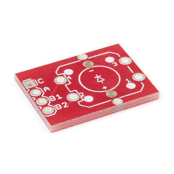
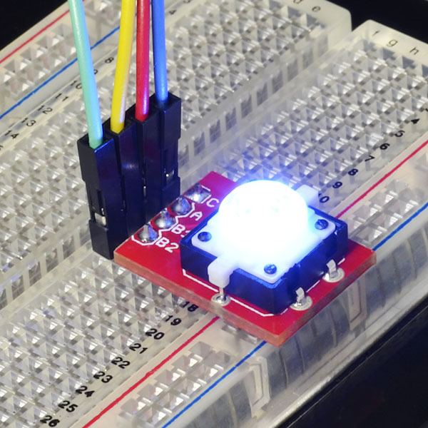
This simple breakout board makes it easy to use our LED tactile switches in a breadboard, or your next project.
Note: Populate the board according to the polarity of the LED on the switch. The markings for the switch are irrelevant and can be reversed.
LED Tactile Button Breakout Product Help and Resources
The ClockClock Project
October 8, 2020
Tell the time with this fantastic Alchitry project using clocks to make a clock!
Core Skill: Soldering
This skill defines how difficult the soldering is on a particular product. It might be a couple simple solder joints, or require special reflow tools.
Skill Level: Rookie - The number of pins increases, and you will have to determine polarity of components and some of the components might be a bit trickier or close together. You might need solder wick or flux.
See all skill levels
Comments
Looking for answers to technical questions?
We welcome your comments and suggestions below. However, if you are looking for solutions to technical questions please see our Technical Assistance page.
Customer Reviews
No reviews yet.
Hi I need an help, it is not clear to me how to connect the wires... I am using a x-OSC board (3.3 V), not arduino. I connect the A to voltage, C to pulldown (10k resistor) and then to GND. In this way the led is always on.... What I am doing wrong? And how/where I connect B1 and B2? Thanks in advance
A and C are the anode and cathode of the LED. While a pulldown resistor is not needed for LEDs a current limiting resisitor is. Usually a 330 ohm resistor is used. which should limit the current to 5-20mA depending on the LED forward voltage and the VCC being used. With 10k, I'm guessing your LED is very dim if you can see it at all. If you want to control the LED from your microconroller you can connect either C or A to an output and when you pull that pin low or high respectively the LED should turn on. As for B1 and B2 those are the 2 sides of the button. Basically when the button is pressed the 2 pins are connected and power flows between them. The standard configuration for a button is to have the microcontroller input on one of the pins and GND on the other. That way when the button is pressed the microcontroller is pulled to ground. You will also want a pullup resistor on the pin connected to the microcontroller so that when the button is not pressed that pin is pulled up and not just floating. If you have any other questions feel free to contact our techsupport team.
I agree that it will work either way, but it's annoying that I followed the markings and had to spend time debugging it.
You really should make a note in the product listing until you fix the silkscreen.
Ah ok, the numbering isn't consistent with the anode and cathode labels. Follow the labeling for anode and cathode and you'll be fine.
Why do we need a breakout for a freaking button?
The LED button is easier to use this way.
so you can (easily) use it with a breadboard as shown in the last picture...
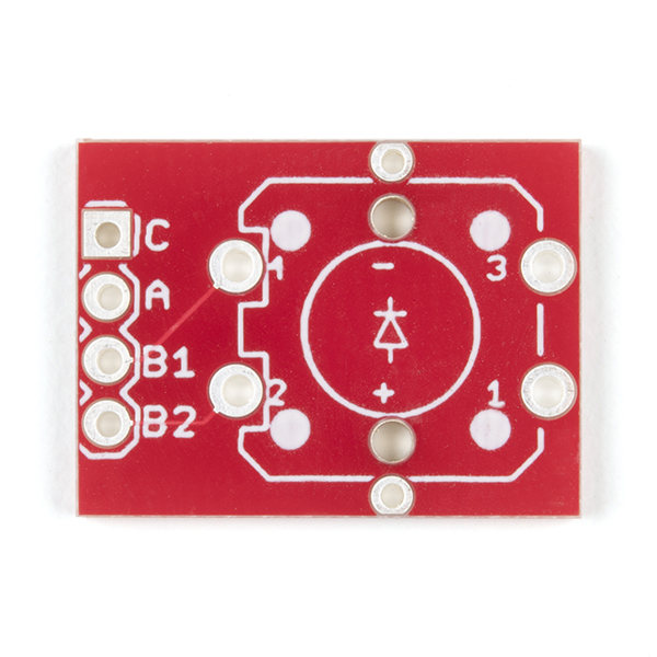
BEWARE ! Numbering nomenclature on the printed circuit board is incorrect!
#4 on the board should be #1, #2 on the board should be #3,
#3 on the board should be #2, #1 on the board should be #4,
OR ... you can look at it in another way: the numbering is correct but the cathode / anode markings on the board is reversed.
Either way ....
Check out the polarity of the diode on the LED switch and numbering before you place it on the board and solder it!!! Other than that, this is a nice convenient board to use. I recommend it.
The board will work either way-you just need to make sure that your power in is wired correctly.
The markings on the board is correct. The eagle file is not matching the board. The tactile switch in this eagle file has incorrect LED pin markings. I grabbed part from this eagle file and used in a design and has few boards that is messed up, I have LEDs that are ON all the time as I was driving it along with 7-seg displays.The part in sparkfun eagle library (TACTILE-PTH-LED-12MM & EZ) are correct. Sparkfun, please update/remove eagle file in this page..
We are getting them updated, but keep in mind the files that are posted are the same circuit as the board. The difference is that the C/A headers are reversed, but the connections on the LED are also reversed. As I said, you can use the board either way, you just need to make sure you wire in power to the LED correctly.
What resistor would I need on the LED terminal if the LED is powered by a 3.3v Lilypad on a 40mA Digital Out?
G'day, would be nice if this board had provisions for a current limiting resistor :)
I cut the trace to the cathode and soldered on a 120 ohm 1206smd. It seems to work though pads would have made it easier. it would also be nice to have pads to jumper Gnd or Vcc to one side of the switch.
But then the board would be larger :)
It is my understanding that you wouldn't necessarily use this as a stand-alone board in a project (if it were, it would do well with a mounting hole, for one), but specifically for use on a typical breadboard. This makes sense, as the pins overlap in a breadboard's columns, but are too close together to fit across the DIP channels to separate them. If it's in a breadboard, adding resistors is usually not a problem :)
I can not download the file because it opens an eagle another page with several characters, someone can give me a download link?
Sorry for such a novice question, but I'm just starting in this world. :) How are you supposed to connect this to an Arduino? I suppose C goes to GND, A to 5V, but... B1 and B2? thanks
Sparkfun stole my formatting...
A little late, but maybe you still need the info. If you are sourcing current to the LED from the Arduino: C - GND A - Arduino through current limiting resistor B1 - GND B2 - Arduino with pull-up resistor (10K connected to 5V)
Set ledPin to OUTPUT Set buttonPin to INPUT
digitalWrite(ledPin, HIGH); //turn on LED digitalWrite(ledPin, LOW); //turn off LED
B2 is the button output, also the input for the Arduino; pushing the button sends buttonPin LOW.
Hi,
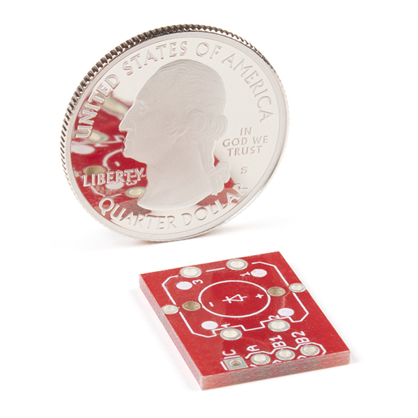
Are you able to include the dimensions of this breakout?