- Home
- Product Categories
- Flex / Force
- SparkFun Qwiic Flex Glove Controller

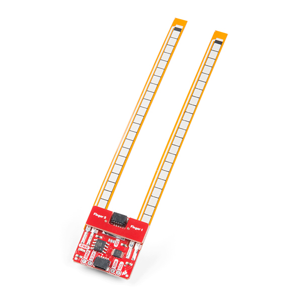
SparkFun Qwiic Flex Glove Controller
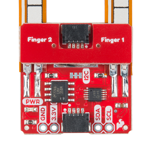
Flex sensors are great for telling how bent something is in a project, but we’ve been running into issues with durability when using them in wearable applications like gloves. The SparkFun Qwiic Flex Glove Controller isolates the weak point on each flex sensor to allow for more permanent applications. Essentially, this board allows you to incorporate flex sensors into a glove to control lighting, sound, and other effects making it perfect for wearable and e-textile applications! To make it even easier to use this controller, all communication is enacted exclusively via I2C, utilizing our handy Qwiic system. However, we still have broken out 0.1" spaced pins in case you prefer to use a breadboard.
The Qwiic Flex Glove Controller has been equipped with an on-board ADS1015 ADC to I2C chip, that way you will be able to get a multitude of analog inputs without needing to touch the microcontroller’s ADC pins. If you plan to incorporate this controller board into gloves (since that is what it was originally designed for) to get sensors on eight fingers (thumbs not included), you will need four Qwiic Flex Glove Controllers. With two gloves equipped with these boards you can even begin making your own VR glove controllers! If you have four controllers on the same I2C bus, you’ll need to use every address available to the ADS1015, luckily there are four available!
Note: The I2C address of the Flex Glove is 0x48 and is jumper selectable to 0x49, 0x4A, 0x4B. A multiplexer/Mux is required to communicate to multiple Flex Glove sensors on a single bus. If you need to use more than one Flex Glove sensor consider using the Qwiic Mux Breakout.
The SparkFun Qwiic Connect System is an ecosystem of I2C sensors, actuators, shields and cables that make prototyping faster and less prone to error. All Qwiic-enabled boards use a common 1mm pitch, 4-pin JST connector. This reduces the amount of required PCB space, and polarized connections mean you can’t hook it up wrong.
- Operating Voltage: 2.0V - 5.5V
- Operating Temperature: -40°C - 125°C
- Resolution: 12 bit
- Sample Rate: 128Hz - 3.3kHz
- Current Consumption: 150µA (Typ.)
- I2C Address: 0x48 (default), 0x49, 0x4A, 0x4B
- 2x Sewing Holes
- 2x Qwiic connectors
- Schematic
- Eagle Files
- Hookup Guide
- Datasheet (ADS1015)
- Qwiic Page
- GitHub
SparkFun Qwiic Flex Glove Controller Product Help and Resources
Qwiic Flex Glove Controller Hookup Guide
July 19, 2018
Is your finger bent? Is your finger straight? The Qwiic Flex Glove controller board will answer this age old question for you with the flex sensor!
Core Skill: DIY
Whether it's for assembling a kit, hacking an enclosure, or creating your own parts; the DIY skill is all about knowing how to use tools and the techniques associated with them.
Skill Level: Noob - Basic assembly is required. You may need to provide your own basic tools like a screwdriver, hammer or scissors. Power tools or custom parts are not required. Instructions will be included and easy to follow. Sewing may be required, but only with included patterns.
See all skill levels
Core Skill: Programming
If a board needs code or communicates somehow, you're going to need to know how to program or interface with it. The programming skill is all about communication and code.
Skill Level: Competent - The toolchain for programming is a bit more complex and will examples may not be explicitly provided for you. You will be required to have a fundamental knowledge of programming and be required to provide your own code. You may need to modify existing libraries or code to work with your specific hardware. Sensor and hardware interfaces will be SPI or I2C.
See all skill levels
Core Skill: Electrical Prototyping
If it requires power, you need to know how much, what all the pins do, and how to hook it up. You may need to reference datasheets, schematics, and know the ins and outs of electronics.
Skill Level: Rookie - You may be required to know a bit more about the component, such as orientation, or how to hook it up, in addition to power requirements. You will need to understand polarized components.
See all skill levels
Comments
Looking for answers to technical questions?
We welcome your comments and suggestions below. However, if you are looking for solutions to technical questions please see our Technical Assistance page.
Customer Reviews
No reviews yet.
This board has several electrical design issues... 1) There is no decoupling cap on the opamp VCC and 2) in a resting state, the resistive voltage divider is 10:1 which outputs 3V with 3.3VCC. The opamp in this circuit has an input common mode range to VCC - 1V, which results in the output slamming the VCC rail for most of the flex range. 3) the saturated output isn't even predictable due to non-linearity, so I don't know how the calibration is even supposed to help
All great points, this was my first ever design and I admittedly didn't really know what I was doing and have kind of been kicking myself ever since. I'll put together a revision now that it's been brought to my attention again. I think I could probably remove the Op amp altogether due to the internal PGA on the ADS1015. I'll also change that resistor divider to allow for a larger voltage swing
Hello, I am a French student. For my end-of-year project, I decided to make a bionic hand controlled by your Flex Sensors (qwiic flex glove) . But I have a small problem, I don't have a shield and I would like to connect two flex sensors to an arduino card (for information I had to make some modifications in order to connect the flex sensor without the appropriate wire). But when I plug both the card (or code) only detects one flex sensor and not the other. These are my connections:
1st flex sensor: SDA - SCL - GND - 3.3V 2nd flex sensor: A5 - A4 - GND - 3.3V
Please Help me, Thanks :)
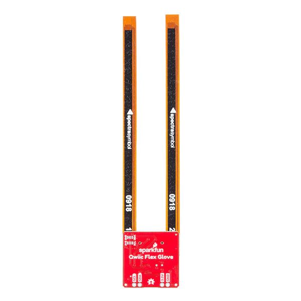
You can connect both sensors to sda and scl, just make sure they have different addresses selected using the jumpers on the back of the board
how can I use the Jumpers ? Sorry, I am not am not a pro in arduino.
Check out the hookup guide for the flex sensor
Sorry, after reading, I don't know where I can change the adress
It should be in there under hardware overview. In the hookup guide for the product that you are using
certain but it is not explained simply, pls help me
Hi there! Looks like you're needing more assistance than we can provide in the comments section. I would encourage you to post your questions in our fourm for this part.
Ok thank you
Can I safely desolder one of the two flex sensors and reattach it later? Or is there a reason that would be a bad idea?
No problem, just be very careful that all the solder is melted before you pull anything off as you run the risk of tearing off the copper pads. I'd recommend a higher than average temp due to the sheer amount of metal