- Home
- Product Categories
- Battery
- 5V DC to DC Step Up - VPack PCB

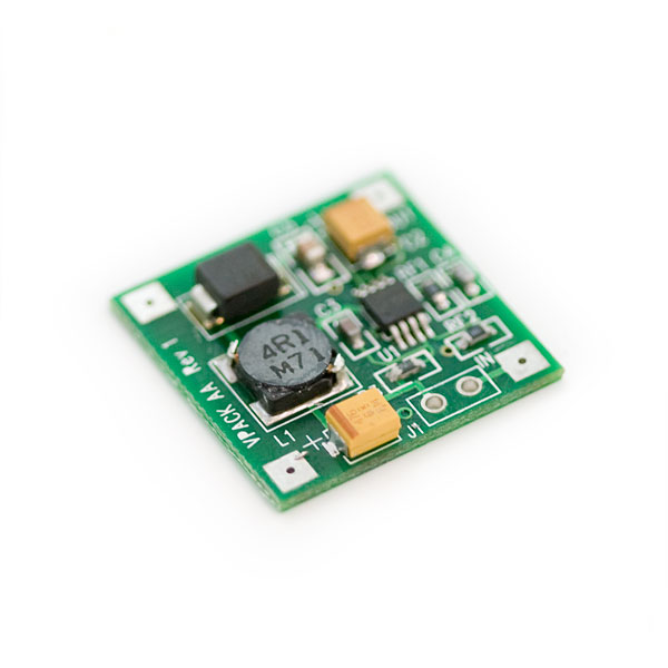
5V DC to DC Step Up - VPack PCB
The is a wonderfully simple 5V power source from Bodhilabs. This PCB uses a source of 1.1V to 4.5V and generates 5V using a DC to DC step up circuit. An empty footprint for a manual or wire jumper is provided on the unit to connect and disconnect power to the circuit. Perfect for all those 5V applications that need to be small, and run on less than 300mA from a variety of power cells.
Specifications:
- Voltage regulation: +5V +/-3%
- Typical current: 300mA or less.
- Typical ripple: 150mV peak-peak (*) @ 135kHz
5V DC to DC Step Up - VPack PCB Product Help and Resources
Core Skill: Electrical Prototyping
If it requires power, you need to know how much, what all the pins do, and how to hook it up. You may need to reference datasheets, schematics, and know the ins and outs of electronics.
Skill Level: Rookie - You may be required to know a bit more about the component, such as orientation, or how to hook it up, in addition to power requirements. You will need to understand polarized components.
See all skill levels
Comments
Looking for answers to technical questions?
We welcome your comments and suggestions below. However, if you are looking for solutions to technical questions please see our Technical Assistance page.
Customer Reviews
No reviews yet.
Never mind, found the data sheet...here it is for anyone that may need it... the IC is an LM2623MM, from National Semiconductor. (Correct me if you disagree) and you can find the datasheet here...
http://pdf1.alldatasheet.com/datasheet-pdf/view/8760/NSC/LM2623MM.html
is this pre-assembled or a kit?
this will be my 1st purchase here and i don't see any clues anywhere as to if the products are self-assembly kits or pre-assembled products.
It comes Pre-assembled.
If 300 mA aint enough for your project(s), I'd suggest you buy these parts instead of this 5V DC to DC Step Up - VPack PCB board:
- http://www.sparkfun.com/commerce/product_info.php?products_id=8484
(2 of em so you get 7.4 volts, so you can use a voltage regulator on it)
- http://www.sparkfun.com/commerce/product_info.php?products_id=107
(Voltage regulator, this voltage regulator is able to handle up to 1.5 Amps flowing through it)
- http://www.sparkfun.com/commerce/product_info.php?products_id=121
(Heatsink to prevent the voltage ragulator to overheat when pulling more than 1 Amps from it)
With these parts you are able to provide 5V and 1.5 Amps to your project(s). this might come handy if you want to add some relays to your ect. USB 32-Bit Whacker :]
The only problem with this setup is the inability to charge the batteries in series. You'd have to disconnect the batteries and charge them one at a time with a LiPoly charger.
...unless there's another way to charge the batteries in series? Or perhaps rig up some sort of software switching control via a microcontroller to swap which battery is connected to the LiPoly charger (now that's an idea!).
Did you figure out a way to do this? I'd like a 5V or 6V source, these are my options:
1. Step up a single 3.7V LiPo
2. Regulate 2 3.7V LiPos in series (how would this charge?)
3. Find some 5/6V rechargeable battery
hmmm...
Also, this would defeat the purpose of the board.<br />
You can always parallel power supplies, aka "gang" power supplies, unless they are unrighteously inductive and cause each other to resonate. The output diode, present on most of these charge pumps, should take care of that.
POLOLU's tunable 2.5 to 9v reg pulls 1.5mA thru 1Mohm, 1.575 through 320Kohm. Testing this specific model now.
Using the electric imp with this board to power HC_Sr04 ultrasonic sensor. Hooked into to an independent power source and got the 5v out, but when powered by the imp it only outs 1v.
I set up my Arduino Micro with this step up powered by 2 AA batteries and plugged into the 5V and GND. Can I leave it plugged into 5V and GND with the batteries switched off when I plug the Arduino into the USB or would the 5V output of the Arduino cause problems in the step up?
AA Batteries --/--> 5V DC Step Up ----> Arduino 5V & GND <---- Arduino Reg <---- USB
It's not on the datasheet, but this requires a start up current of ~1A. From the manufacturer:
I was confused why it was only outputting ~2V when I gave it 3.3V from my Uno, this is why.
It looks to use this, a connector is needed for the battery: https://www.sparkfun.com/products/9749 And a header for jumper cables has to be soldered on for connecting to a breadboard.
Does this sound right? It seems downright inconvenient. Is there a board with the right connectors?
If you'd rather have a board with a Lipo connector built into it, take a look at our LiPower board. It's also available with a charger built into it.
Hey guys I hope I can get some advice here:
I need to design a custom step-up for my project.
I will be using a Li-ion battery pack, 3.7V at 1400mAH. I need to step it up to 5 - 5.5 volts, running up to 5A. It will never be a steady 5A.
I have looked for tutorials, design examples but can't seem to find anything sufficient.
Any help is greatly appreciated!
Late reply, but try National Semiconductor's WEBENCH tools. You put in your requirements, and it gives you a bunch of design options (if it can) including schematics, BOMs, efficiencies, etc. Very cool, and all web-based. Good luck!
Does anyone know the minimum power required to use these step ups? For instance, at 1V, what is the minimum current needed to step up to 5V?
I will add that my method still has a high startup current of about an amp, but for a much shorter period of time than what the provided resistor set delivers.
For those experiencing startup problems with this board I DO NOT recommend using the method posed by "Frustrated" below as this is probably why he is getting bad ripple. I get good performance with my method. DO NOT FOLLOW THE DATASHEET for setting ouput voltage. They have this thing set with RF2 at 100k, and I get much faster startup with virtually no current sap if I use 75K, and then ALSO change RF1 to set the output voltage. Note that I am using 1.5V input, and still get a sort of current sap with input of 1.2, so perhaps at 1.2V input RF2 should be reduced to 50k ohm. I believe the startup conditions are heavily set by the total resistance in the RF1 - RF2 resistor set. Use a lower resistance there for lower input voltages (I think). The LM2623 recommends RF2 is somewhere between 50k and 100k. The correct equation is found on the LM2623 datasheet. It is RF1 = RF2*(Vout/1.24 - 1) Have fun!
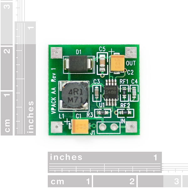
Can anyone tell me how to connect J1 the Wire Jumper? I dont know how to connect it.?
Can anyone tell me what Zenerdiode is used for D1 and what is the value for R3 and C5???
Mine broke after about 3 hours of converting 3.7v to 5v.
It now outputs about 1-2 volts.
anyone knows how to modify this pcb and get out 500mA or more?its important because of the dimensions,i need something verry small
Just got the Vpack PCB and I'm having problems. After hooking up the Jumper to activate the circuit, I'm only getting 1V at output terminals with a 3V Button battery hooked up to the input.
Any ideas?
My current confusion comes from the detail that C1 and J1 appear to be switched in the datasheet. Makes it rather difficult to reverse engineer a working schematic from this widget
this might answer my question
http://power-topics.blogspot.com/2009/07/operating-power-supplies-in-series.html
uses diodes
Does anyone know if 2 (or more) of these can be arranged in series to get multiples of 5V outputs? I tried it with the 1400 series dc-dc converters and it hasn't worked so far. Thanks
For those of you having the shorting issue, I resolved this by moving the EN pin from OUT to IN.
Steps:
1) Desolder and lift the left side of the LM2623. I slid a thin wire under all four pads and gently pulled as I heated the whole row of pins.
2) Cut the trace under the LM2623 that goes from Pin2 to Pin7.
3) Resolder the left row of LM2623.
4) TEST to make sure there are no shorts.
5) Gently solder a thin wire (like wire-wrap wire) between Pin2 and Vin. I soldered directly to the Jumper.
4) TEST again to make sure there are no shorts (there were for me).
That's all. It works fine now, draws far less power on startup, and handles temporary shorts without issue. Next, I'll probably remove the jumper, solder the IN directly to the jumper hole and use the IN pad to expose the EN pin so I can control power remotely.
As an aside, this board is pretty crappy. Really bad ripple and the designer didn't leave enough physical room for a larger output capacitor if you want to fix the ripple. The NCP1400 board is a far more stable supply.
Just to say thank you! I was going crazy with this problem (in my case it was slightly different: the load at the output is so high, that the EN was never enabled and the board was pumping 1.5A from the batteries... I did as you suggest, and it worked... (I did not de-solder the surface mounted chip, but get to the connection from the other side using a drill - probably as difficult if not more than your advice). Yes, pretty crappy board I must say.
Thanks again
which is better mintyboost or this circuit?
Hey guys, is there something special I need to do in order to get this to work? I've hooked it up correctly (I believe). I've tried a AAA battery, power supply voltages from 1-4V, and still get nothing (0v) on the output. I've tried it with loads and open output. I tried a second unit and couldn't get that one to work either. Is there something I'm missing? (board Rev 1, datestamp: 0913)
Yep, you are missing the J1 jumper. It needs to be jumpered to turn on.
what do we have to do exactly with those J1 jumpers ?to enable the chip
iam getting exactly same problem
Thanks! The J1 jumper did it.
It seems this board's layout is slightly different to the one on Bodhilabs page: VPackPCBAA, The placement of 2 pads and J1 and C1 are reversed. Other than that I assume the components are the same.
Using this 5V VPack PCB with only TWO AA batteries, it seems to work as advertised, you get a nice 5V at the output.
I was seeing a similar issue to the one jbfraser described; it seemed to short out the supply. Using 4AA batteries, with a separate 3.3V regulator, the 3.3V regulator got really hot when this VPack was placed inline; the output of the 5V VPack PCB was near 1V.
In looking at the datasheet for the LM2623, ghjeng was nice enough to provide, it seems this problem might due to that C3 capacitor described in the design notes on datasheet: LM2623 Datasheet, pg. 11. SCH on pg 1.
I guess the combination of the input impedance/capacitance to this board causes some really freaky behavior as I saw in my situation; I'll have to dig deeper and try out some other components. I wouldn't call it a "drop in" component.
Erg. Some frustration here.
I'm just starting to look at this module. One thing I wanted to check was quiescent current.
In trying to measure that, I keep getting the module into a mode where it's basically shorting out the supply.
It seems to happen when I've got absolutely no load (no connection) on the output. Then if I take the input voltage down to zero and bring it back up, the input is pretty much shorted; I blew the fuse on my multimeter verifying this.
I don't get it: somehow this gets into a mode where it is taking >300 mA if allowed.
By the way, the quiescent current when things are going well is .24 mA @3V, .17mA @ 4V, and .34mA @ 2V input.
Any ideas on avoiding short out the battery mode?
(All testing so far was with bench power supply, so maybe the internal resistance of a battery might help?)
jf
Well, my suspicion is looking plausible. In the datasheet, the enable pin on the IC is connected to the 5V output. This appears to be a design problem and would explain my particular problem. If you short the output, the EN pin is pulled low, disabling the output voltage. Without the output voltage (5V), the EN pin cannot be set again, causing the unit to sit in a locked 'OFF' state. This persists until, say, you touch your statically charged finger the the output, which switched the EN pin, just long enough for the unit to charge up the output voltage again and hold it 'ON'. If anyone disagrees, let me know, but that is what I think is happening and if so, it appears that you would need a design revision to get around the problem.
Can anyone tell me what the charge pump IC on this board is?? I am having a problem where, if I short circuit the outputs, the unit will not start working again unless I touch one of the ground pads with my finger!! This appears to produce a static voltage spike which is resetting the IC?? I am wanting to see the IC data sheet to see if this is a possibility and to troubleshoot my problem. Any suggestions?
Anyone know how hot this runs when it is providing 300ma ?
Is there anything I can do to get this up to 400 mA with 5V?
What if I want more than 300mA?
Is the chip limiting it? What is its reference number?
I would like to use the 6Ah Sparkfun battery running at 3.7V and would like 5V and 500mA as an output (USB voltage). Do you think it is going to work?
Thanks,
Mike
Chip reference is LM2623 with a switching current limit of 1.2 Amps.
Then, powered by 2 AA cells, theoretical maximum output current is :
Vin * Ilimit * Efficiency@Vin / Vout =
(2*1,5) * 1,2 * 0,8 / 5 = 576mA
With a 3,7v Lipo, it's even better (in theory) :
3,7 * 1,2 * 0,85 / 5 = 755mA
But yes, with only one AA cell, you can't get no more than ~280mA
ByNico:
assuming your Lipo cell is at least 400mA capable, yes you'd be safe. (do not exceed 2C of discharge rate)
I'm currently using this converter to power a stack of arduino & shields for a total of 620mA @ 5V and I'm using a 2000mA 3.7V lipo cell.
And there's no signs of overheat or unstability on the converter.
this can handle usb power due to the usb standards require the device to request for more than 100 ma from the host, and most items I found pull no more than 250 ma from usb, ex: usb mouse/keyboard 80ma each , iphone charging 245ma not charging 70ma,thumb drive 150ma, few exceptions bus powered ext harddrive/dvddrive 400ma each
I'd like to power a 3.3V part (the WiFly GSX board sold here). Can anyone recommend a good LDO to go from 3.7 to 3.3V? I've been looking at the MC33375D at Mouser but it's not available yet..
is possible to power an usb device with this? let's say an mobile phone?
or maybe is it possilbe to connect them parallel?
Dang it! They redesigned the board and the datasheet still does not include quiescent current. If there is no output load connected, there is still some power used regardless of the approximating equation in the datasheet. How much is the quiescent current?