- Home
- Product Categories
- Sensors
- 9 Degrees of Freedom - Sensor Stick (Old-School)

9 Degrees of Freedom - Sensor Stick (Old-School)
Replacement:SEN-10724. The new revision replaces the HMC5843 with the HMC5883L. This page is for reference only.
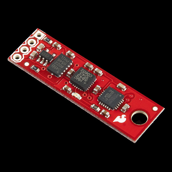
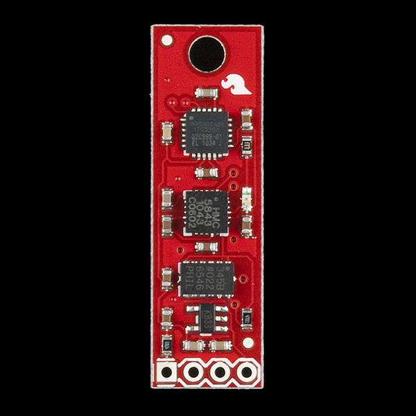
The 9DOF Sensor stick is a very small sensor board with 9 degrees of freedom. It includes the ADXL345 accelerometer, the HMC5843 magnetometer, and the ITG-3200 gyro. The 'stick' has a simple I2C interface and a mounting hole for attaching it to your project. Also, the board is a mere 0.036" thick (0.093" overall), allowing it to be easily mounted in just about any application.
**Replaces: **SEN-10183
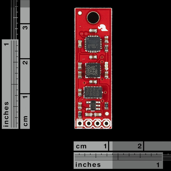
- 1.37x0.42"
- Schematic
- Eagle Files
- Datasheet (ADXL345)
- Datasheet (HMC5843)
- Datasheet (ITG-3200)
Comments
Looking for answers to technical questions?
We welcome your comments and suggestions below. However, if you are looking for solutions to technical questions please see our Technical Assistance page.
Customer Reviews
No reviews yet.
Dear Sparkfun, is it possible to foreseen a date when this item would be available?
Thanks.
Yes, an update on when this is available again would be great.
+1
+1 Have one of these in my shopping cart right now and need to order parts in the next two weeks or so, wondering if it's going to be available before then? Any hints?
+1
+∞
Come on guys, what's up with this IMU?
+1
I've now had 2 of these units. The first one had a unresponsive ITG-3200, so I contacted Sparkfun and was told to send the unit in for testing, then they would send me a replacement. However, since they were out of stock I had to wait a while.
Yesterday, I got the replacement unit and immediately hooked it up to my test rig. This time, both the ADXL345 and the HMC5843 was unresponsive. Although, the ITG-3200 worked fine.
Is there something in the making of these units that fry the chips or something?
At least I know that my test code works for all tree chips....
Hi WAAV,
Did you ever resolve this issue?
I'm having what seems like the same problem. I can communicate with the ITG-3200 fine, but get nothing from the other two devices.
Is there any news on when the board will be available? Could someone at least give a rough estimate of when the new version will be ready (are we looking at days, weeks, or months?).
It is very important to me to have an estimation of the availability of this item, is it 1 month, 2 month or 1 week?
I appreciate very much,
Thanks.
Hey any updates on when this product will be back in stock?
Noise on this version SEN-10321. In case any of you have the same noise problem, Ill try to save you some time. I have encountered about 30 counts of noise on the accelerometer. Spent a lot of time trying to "fix" my i2c I/F software which is fine. Turns out there is a nasty ripple on the 3.3v at the i2c clock freq (400khz in my case). Added a 10uf electrolitic cap at the regulator output (parallel the existing), and it knocked the noise way down to just 2 or 3 LSB.
I have to put a mechanical pressure on the hmc5843 to make it work
first tryed 100 uf capa, then find out it works when i put mij finger on the print.....
Now it works with a crocodile ???? clips !!!! / paper clip pressing on the middel ic (hmc5843)....
When clip removed it stop working
Can every body try this please
And now?
Definitely contact techsupport@sparkfun.com.
I have found the same occurs with both the accelerometer and magnetometer.
If I use a paper clip, the devices work fine and when the paper clip is removed, they stop working.
Unfortunately Luyten you are right, i had your problem and i did that same test a week ago, sorry if i didn't post that here it might have saved you some time, however i posted it in the forums, anyway your only solution is to get replacements (that's what i did) cause it's hard to fix( don't try it), so i suggest you contact techsupport as soon as you can, before they runout of parts, and they'll take care of that.
could you please shear with us what fixes are to be included in the new version?
The only change will be to use the HMC5883 instead of the HMC5843.
what are the differences?
HMC5883 is a bit faster, it works at 75Hz while HMC5843 was 50Hz max, the magnetic range is wider, it measures up to 8 guass, HMC5843 was 4 guass, however you won't be needing that much, but it's selectable anyway, the default selected range is fine which is about 1 guass for both, they have the same i2c address, same registers, same setup, so the good thing you don't have to change anything in your program.
That's not entirely true. Y and Z register axis are swapped in the HMC5883L compared to the HMC5843.
Also note that the HMC5883L is considerably cheaper than the HMC5843 something which should helps lower the final price of the board.
However, the HMC5883L is really a sucker to solder as it has very small pins and it's very light, absolutely the most difficult chip to solder I ever dealt with. The chip seems to be also quite sensible to high temperatures and when overheated some segisters may stop to work. Detailed 1 day after production tests are suggested to every board assembled.
Hope this helps,
Fabio Varesano
Well, i haven't tried it yet, i just took a quick look at the datasheet, and what a dumb thing to do swapping those registers, but it's good to know anyway, it would have took me some time to figure it out, cause the datasheets seems identical at first glance.
I don't know 100%, but the HMC5883 is a drop in replacement. You can check the datasheet, or google it and find out. I'm not exactly sure, but the HMC5843 is out of production.
Hi all,
I got a few of the sensors stick, tried two so far, for both the accelerometer and Gyro (ADXL & ITG) are working okay, but I get no response from the magnetometer (HMC) it refuses to initialize!
The last comment from WAAV doesn't seem to have been addressed, can someone look into this and advice what is wrong with these sensor sticks???
Waiting for your feedack
I have the same problem with you? I can't read anything from the magnetometer (HMC).
Please give us some advice!
Me too, i can't get the magnetometer to respond, the gyro/acc are working just fine, and i know it's not a code issue cause i have the standalone breakout of the same magnetometer (HMC5843) and it's working fine, but of the magneometer of the stick seems dead to me, i can't even initialize it, am getting no ACK signal from it.
So Sparkfun people, are you sure that the magnetometer of the last lot is working properly or what cause i got a handful of sticks and i can't get the magnetometer to work in any of the sticks, so plz let us know what's the problem as soon as possible.
Please contact techsupport@sparkfun.com. We'll take care of you, we just need to know there's an issue, and walk you through it if there isn't.
I also have the same problem. Applying (hard) pressure to the board to bend it a little inwards helps and shows that nothing is wrong with the software or my circuit. But that is no solution. There must be a kind of soldering error or something like that.
I have the same issue, I'm very disappointed, this is not the first time. I have sent a mail to your support ...
Same here. I have the exact same problem...
whats the word on this?
when are the new batch coming in, and when will this be back in stock?
(We would definitely like may be a barometer stuck in there as well)
Well, let's hope they get the main sensors to work first, and give us functional replacements, then they add whatever they want to add, cause it's very unprofessional to sell untested products like this, i can't beleive i bought 12 of those
They are not untested. All of our internal assemblies are tested before they go out. You might have another issue completely. You guys should contact techsupport@sparkfun.com. I know with the 9dof razor, there are issues where the magentometer doesn't initialize properly under certain conditions. the hardware is fine, but you might need to initialize it differently from the your micro-controller.
any news about these conditions?
if the hardware is fine then what are WE doing wrong?
There are no conditions, and the hardware is not fine, they (techsupport) found out that there "IS" something wrong but they don't know what it is yet, i'll let you know when they know.
thanks a lot:
edi.gotlieb@gmail.com
What kind of conditions, when am telling u that i have the same sensor working under the same conditions with the same microcontroller with the same program in the standalone breakout, and it doesn't in the stick, and it's not that hard to get it to work, i had 7 of those HMC5843 breakouts, and all works just fine, so sorry am not buying the "conditions" excuse/argument.
I sent to techsupport days ago and no response yet
ya im also disappointed and you have every right to mad. I also have to wait now at least 2 weeks until i can resume working on my quadrotor...(i ordered from reseller in Israel)
i agree that this is very unprofessional and will be mentally noted for my next purchase...
I would very much like to here what Sparkfun has to say for it self.
Any chance you can offer a slightly different version of this sensor board with a altimeter on it? Would GPS expansion be a possibility also?
Looks like this is in stock now. Did the HMC5843 get replaced with the HMC5883? If so, please update the description, schematic, Eagle files, (photos ?) and the datasheets.
Nope, it's the same as it was, everything is correct. We haven't yet transitioned to the new IC. we still have plenty of the old ones, it's not quite EOL'd yet.
Did this board every get redesigned, replaced, updated, etc? It's been out of stock for a great period of time... if it's being replaced... I'd really like to see an 9dof with baro as it's replacement (ITG-3200, BMA-180, HMC-5883L, and BMP-085).
Sure would like to pick one up if available?
I second that, would be really nice to see this board with the addition of a barometric pressure sensor.
I've written code for an Arduino that constantly polls the data from the three sensors and pumps it out the serial port. Anyone know a good place to upload it to so others can use it?
Hi Doc,
i'm searching for some code to get data from the stick! i use arduino uno for now but want to try it with the pro mini and if it is possible connect with XBee Explorer Regulated with Zigbee!!!
can you send me some code? so i try it out..
As a head's up, I've copied a bunch of code from different poeple from different places. I didn't think I'd be sharing it when I did this so my bibliography is lacking.
Here's a link to download my code:
dropbox
Hi,
I am looking for information about a retired sensor stick
(SEN 10183).
I have seen a lot of information about each module separately but i couldn't find any info about the sensor stick as a whole.
Can someone tell me how to extract data from the device?
is there a written code i can use?
Do I need a specific micro controller to work with the sensor stick?
Thanks a lot,
Omry
Any microcontroller will do, many people here use Arduino ones and I myself have gotten this stick working with an Arduino UNO.
Is there someone who could share some code, on how to use the 9DOF sensor. I'm working on the PIC32 platform. Curently i'm trying to read data from the accelerometer using I2C but all i'm getting is a constant value of 255. Anyone who had this before ?
Any help would be greatly appreciated.
I using 9dof stick with Arduino MiniPro, Jennic5148 and LPC1343 (32 bin ARM coretx 3 micro).
If you want I can provide my libraries as they are, up to you to adapt to your PIC32.
Paolo.
Any word on when this will be available again? I have (had) one... would love to get another.
I finally gave up and build my own board...much cheaper much smaller and much controllable....
I know this won't help you much.
I'm trying to get this part to talk to a 3.3 V 8 MHz Arduino Pro Mini and I have similar problems that have been mentioned on this. Looking with a scope, the Arduino seems not to pull the I2C lines low ever. However if I disconnect everything and turn that pin into an output, it wiggles it high and low just fine. I did what NoWorries suggested with internal pullups and it only causes the program to freeze elsewhere (never gets past the initial I2C writes to configure devices). I also tried other's published codes for the 3 sensors with no luck. I switched Arduino Pro Minis and that doesn't fix it either, and I checked pin-to-pin continuity for the SDA and SCL lines on all parts involved. Any suggestion? While it doesn't fix the problem, I find it odd that changing the internal pullups line in TWI.c changes where the program fails. Is there a problem with Wire library on the 3.3 V minis?
I'm using imu 9dof stick of sparkfun with an arduino pro mini 328.
This is a 3.3V device so there is no incompatibility with I2C bus logic levels.
But it is very important to use a couple of pull-up resistors on SCL and SDA lines. By the way, just to be sure, SCL and SDA are A5 and A4 respectively (see http://www.arduino.cc/en/Main/ArduinoBoardProMini).
If you want I can share with you my arduino code?
Paolo.
Hi Paolo hi devangel77b,
i want to use the 9dof sensor stick of sparkfun with an arduino pro mini 328, too. But i do not really know how should i put it together, do i need any resistors because both are 3.3V? Can you give me any tips how i can connect the board with sensor stick or a schematic. For the beginning i connected Arduino Uno with the stick to grab any data. (Connection from Arduino to Stick: 3.3V and AREF to VCC, GND to GND, SDA to A4 and SCL to A5) Is that correct?
Thanks a lot,
Belushi
The pull-up resistors are already on the 9dof sensor stick, so you do not need anything else.
Pullup resistors are always required on I2C bus, a logic level adapter is required if you are not working with 3.3V.
And this is not a matter of power supply of the stick, but a matter with I2C logic levels.
If we are talking about using ArduinoMini Pro, just connect VCC with VCC, GND with GND, SDA to A4 and SCL to A5.
To note that the address of ITG on 9dof stick is 0x68 and not 0x69 as in the breakout boud for ITG3200.
You can find lot of info here: http://www.varesano.net/
Paolo.
Is it possible to at least give an estimate of the time it will be available?!
The suspense is a killer...
When will this item be available again??
Has anyone gotten this to work with 3.3V VCC? I'm interfacing it directly to an ATMega328 running at 3.3V, using Arduino firmware and the Wire library, and I can't talk to the accelerometer.
I've tried everything -- all possible I2C addresses, writing 0, 16, and 8 to register 0x2d, slowing down the bus, adding delays, etc. All I ever get from the device is zeros (in fact, Wire.available() returns 0, so it's not even responding).
At this point, I think either it won't work with 3.3 Volts, or it's dead. Since the other two sensors on the stick work, and the ADXL345 should be good down to 2.0V, well below what the regulator would drop 3.3 to, I'm tending towards the latter.
I'm working with 3.6v as input voltage and a 3.3 voltage regulator on the board without problems.
I also replaced the 3.3 voltage regulator with a 2.8 voltage regulator (it looks to me adxl345 is working better with lower tension) and all three sensors were still working good.
Paolo.
Atmel store has a version of this for $54
http://store.atmel.com/PartDetail.aspx?q=p:10500250
Does anyone know the pitch of the connecting holes, i.e. how far apart each one is from one another?
It's standard breadboard spacing, 100 mils (1/10 inch).
Hello everyone.
I have a problem with my 9DOF Sensor Sick.
The accelerometer and the gyro works fin, but the magnetometer return always the same values.
I use this code to read the values:
http://www.fezzer.com/project/227/sparkfun-stick-imu-driver/
Can anybody tells me what i doing wrong?
Thanks for your help
I have purchased sku: SEN-10321; 9 Degrees of Freedom - Sensor Stick. What do I need to purchase to read the data and download it to my computer? I have an Open Log attached to it but it is not reading the info after the flight. Any help or suggestions would be greatly appreciated.
I've just received mine some days ago, was the first time i play with I²C devices.
I'm using an Arduino board with a protoshield, makes a very straightforward prototyping platform with a large community so there are a lot of examples on the net for reading I²C devices and printing the output to serial (in fact serial over USB) console text.
Makes it an easy trasition to standalone ATmega TQFP32 platform when you have a production-ready design (and lightweight requirement i suppose)
I've found this for the accelerometer:
http://codeyoung.blogspot.com/2009/11/adxl345-accelerometer-breakout-board.html
I've adapted it a bit to read also the gyro and compass values.
Now those are raw values but i'm in the process of writing a small unit to init at optimal settings and output values as SI units.
For the Open Log i just cheched it's page and i can only backup Nate's reply to your comment, neither hard nor trivial.
I have a hard time reading sensible data from the Magnetometer. I cant seem to make it work.
Gyro and accelerometer data is read fine.
I initialize it all right, but the data I get out is always pointing in the same general direction. Its mooving a bit, but not as I expect.
Where should the vector point? Straight north?
Is it very sensitive to being mounted in a breadboard? I have a few jumper cables within 5 cm raneg of the sensor?
I have tried estimating a bias, by reading max and min of sampled values. I remember having a phone that needed to be rotated to use the compass, and assume this is the same sort of sensor.
I see the same behavior from two different units.
I hope someone can suggest what I am doing wrong.
Kind regards
Tax
Magnetometer and Accelerometer MUST be calibrated first (i don't know about Gyro) Calibration is calculating BIAS and GAIN, that is a Matrix and a Vector of parameters, to "sphericize" and translate the ellipsoid of the RAW value you get from the board.
You can find some info in this PDF (ST):
http://www.st.com/internet/com/TECHNICAL_RESOURCES/TECHNICAL_LITERATURE/APPLICATION_NOTE/CD00269797.pdf
http://www.st.com/internet/analog/product/250145.jsp
The following code if for Matlab, but works also with Octave (free)
THIS IS NOT my code, but i don't remember the link of
the author (sorry) :
http://rapidshare.com/files/449329308/MgnCalibration.zip
What grade of caps does this use? X5R/X7R+?
Can someone help by posting I2C code examples for these chips, or at least one of them to work with Arduino. I can't seem to get it right. On the Serial monitor it reads out random data but I don't think I"m coding it properly.
http://www.varesano.net/blog/fabio/initial-implementation-9-domdof-marg-imu-orientation-filter-adxl345-itg3200-and-hmc5843-a
Check out the various comments on how to adapt my code and sensor fusion to the Sparkfun Stick.
Interesting, this is very helpful. I'm actually getting readable values now, except, I'm not too sure on the units or some values seem to be the same everytime, its possible I think I might have burned out some of the sensors by using a 5V ATMEGA328 when these chips are 3.3v.
The Logic Level Converter is required to make this work with 5V ATMEGA328 chips!
Re connecting to Arduino.
You say (to Member119819 Feb 9th) 'You do need to be certain that the internal weak pullups are disabled however.'
How do I do this?
Thanks
The Wire library's twi.c file is where the pullups are activated. The file is located in the arduino-00xx/libraries/Wire/utility/ directory where xx is the version of the arduino code you are using. The function twi_init(void) is where the weak pullups are activated, so just commenting these lines out will deactivate the pullups. The lines to comment out look like:
sbi(PORTC, 4);
sbi(PORTC, 5);
sbi(PORTD, 0);
sbi(PORTD, 1);
Just put double slashes "//" in front of these lines and the pullups will be deactivated.
Only two of these lines are important for any one particular atmel part, but it is safe to comment all four out for simplicity sake.
Hope this helps.
Looking at the schematic there are no signs of 5volt level conversion. Ths stick uses two 4.7k pullups to 3.3v.
Level conversion is easy anyway.
Search for AN97055 pdf or see link below.
ics.nxp.com/support/documents/interface/pdf/an97055.pdf
I have a question about the I2C interface. Does it support a 5 volt supply? Sorry if this is a newb question.
The I2C interface can be used with a 5 Volt MCU. The 3.3 Volt pullup resistors are within most MCU's logic high threshold. When the sensor pulls the line low, it also will be within the MCU's logic low threshold. When the MCU pulls the line low, the sensor will also see this as a low.
To be sure, read the datasheets on the MCU that you intend to use.
Note: The 5V Arduino works fine when directly connected to the sensor board. You do need to be certain that the internal weak pullups are disabled however. If you do not, you risk exposing the sensors to voltages that they are not specified to allow.
Has the orientation of the magnetometer been changed to be coincidental with the accel & gyro? Is there a plan to fix this in the future?
No, the orientations of the sensors are the same, the only change is that the artwork of the PCB is changed to eliminate the need for a wire on the sensor board.
However, it is trivial to re-assign the axes of the sensors in software.
Hi!
could you please tell us which voltage regulator is on the pcb?
Regards!
The voltage regulator is the SM MIC5205 Series 3.3 V 150 mA.
It would be a piece of art if you added a pressure Sensor
My Unit gives constant values on Gyro and Magnetometer ( x=y=z ) regardless of orientation or time, Accelerometer is not tested sofar. Has anyone an idea ( unit fried?? )
Elias
Is the led on the sensor stick on?
Have you verified that all connections are proper and have the expected voltages on them?
Can you read the device ID's from the sensors? (each sensor has fixed data that can be read to perform a simple check of the sensor)
The accelerometer's is at 0x0, the gyro is at 0x0, the compass has ID's at 0x0A, 0x0B, 0x0C.
Are you using a proven application for reading the sensors or trying to make your own? (Getting an I2C read/write routine to work the first time can be a challenge...)
For instance, if you are incorrectly addressing the sensors, they will never output any data, as they think you are trying to talk to another I2C device.
Hope this helps.
Hi!
How can I find out the I2C address of my sensor stick?
Thanks!
Reading the datasheets and the schematic is how it is typically done...
But, to save you a bit of work, here are the three 7-bit I2C addresses of the sensorstick: Compass = 0x1E, Accel = 0x53, Gyro = 0x68.
Enjoy.
Thanks a lot "noworries"! :-)
Any chance of upgrading to the IMU-3000 instead of the ITG-3200? 2000 degrees/second is more than most hobby applications would want and therefore I think most people would prefer the higher resolution of the programmable-range device (e.g. 500 degrees/second with 4x more resolution and also 3x less noise). The MPU-6000 with fast SPI comms would also be very useful!
The resolution of ITG3200 (acc to the datasheet) is 14.375 LSB/(°/s). It´s mean that it´s can sense 0.07 °/s (1/14.375)!!
Don´t forget that the ITG3200 has a word lenght of 16 bits!!
L. Mauro
In practice, 0.07°/s is quite impossible to be sense because of noise. But noise is a common issue for every device.
I have noticed that Honeywell has indicated that the HMC5843 is an end of life part. They recommend using the HMC5883L in new designs. The new part is smaller and has better resolution. Any plans for an updated version of the sensor stick using the new IC? If you do, I would recommend bringing out the interrupt line of the compass sensor to allow for better update rates than polling via I2C.
Thanks.
Hi!
Can you tell me what the voltage tolerance is on the VCC input of the voltage regulator of the SEN-10321 razor sensor board?
Thanks!!
Hi!
What about add a barometer and possibly gps connection pins?
I am waiting for the MPU-6000 and MPU-6050 devices. Do you guys plan to use those chips in the near future? MPU-6000
We are looking into the MPU-6000, as there have been several requests for it.
Rumor has it, no chips until June or so.
Could you please explain the $10 increase compared with the former SEN-10183 with a blue strap? Thank you.
SEN-10183 was marked down because of the PCB error that required the blue wire correction.
If you take a look at the comments of SEN-10183 you'll see RobertC answer the question "Is the flawed version of the board marked down in price?" with "Yes. It will normally be $99.95.".
Hope this answers your question.
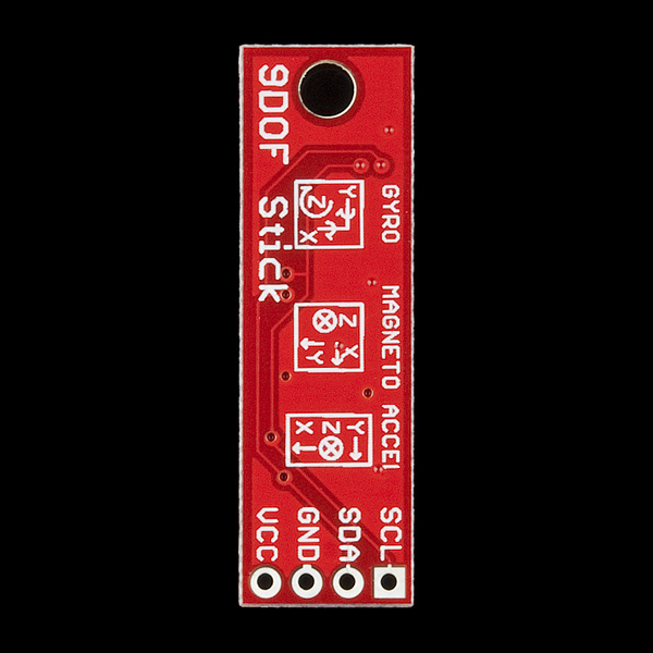
Could we please get a back view of the board?
We are waiting on the first build for these. You can backorder them until we get the first build, which should be in a day or two.