- Home
- Product Categories
- Wireless and IoT
- GE865 Evaluation Board

GE865 Evaluation Board
Replacement: None. We are no longer carrying this evaluation board but have a look at our cellular category for more modules and boards. This page is for reference only.
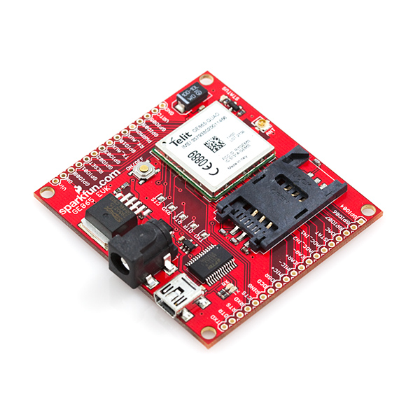
This is a simple to use USB evaluation board for the GE865-Quad cellular module. All pins of the GE865 are broken out, so you'll have access to the state-of-the-art DAC, ADCs and GPIOs. No messy 3.8V regulation. No tricky 3.3V to USB converter. It's all done for you!
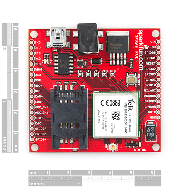
The serial pins are wired up to an FT232RL UART-to-USB bridge. You can plug the GE865 Evaluation Board into any USB port on your computer and it will act just like a standard COM port. Power up the board, turn on the module, and you can start sending and receiving AT commands via a terminal emulator. The USB chip can be disconnected (by clearing all solder jumpers) to allow for external control of the TX and RX pins on the GE865 module (3.0VDC max!).
Power can be provided through either USB or an external power source, via the barrel jack connector or Vin/GND pins (5-9VDC). To turn the module on, hold the ON/OFF button down for 1-2 seconds - just like turning on a cell phone.
Note: Some USB ports cannot source enough current to power the GE865 module. If the power supply is inadequate, the module may shut down while attempting to connect to the cellular network. An external power supply will correct this problem if it is experienced.
The board comes fully assembled with the GE865 module, 3.8V power regulation circuitry, SIM card socket, U.FL antenna connector, and other supporting circuitry. All pins of the GE865 are brought out to two 0.1" headers. 3.8V is regulated through a surface mount SPX29302 LDO regulator.
- 2.3x2.45"
- Schematic
- [Eagle Files](http://cdn.sparkfun.com/datasheets/Cellular/GE865 EVK v13.zip)
- Telit GE865 documentation (hardware guide, AT command set, etc.)
- FTDI USB Drivers
Comments
Looking for answers to technical questions?
We welcome your comments and suggestions below. However, if you are looking for solutions to technical questions please see our Technical Assistance page.
Customer Reviews
No reviews yet.
Why retired ? the GE865 has problems ? I think that sparkfun should also show the reason of retired; tecnical, comp. avalability, etc...
And I just wanted to buy this :-(
What's worse that there is no single product that could replace this board in sparkfun shop.
It looks like this was retired in 2011 and replaced by the SM5100B (which is currently EOL). Check out the new cellular board, it will have different features but is our current cellular offering.
help!!!
noob questions
this board can:
- make phone calls?
- receive phone calls ( if i hook up a mic and a speaker can i use as a basic phone )?
- send sms from a custom arduino command via serial?
thanks.
Hi, recently i buy the ev board in my country to make some experiments, te hyperterminal works fine already sent a SMS and make a call, now i want to send a text to the board and based on the content of the text make an output enabled on I/O ports board, anybody can help me with this need some hints to start to work on it
Hi
I have just received this module:-) I would like to ask you what kind of antenna do you recommend. Can I use the interface cable --> http://www.sparkfun.com/products/9145 and then use a quadband sma antenna? Could I also have a reference to the RF connector on the board? Is it an ipex?
Yours,
D
Any recommendations for a power supply? For development I'm looking for a wall-wart type of connector, but SparkFun is currently out of anything above 600mA, which I am reluctant to use since there is a comment that a USB port might not be sufficient. Is the barrel jack positive or negative center?
Also, I've seen several comments about batteries, anyone successfully use a battery? What type/where did you connect it?
Lipo batteries from here at Sparkfun work well. I recommend getting the 2000mah Lipo battery.
Finally got this module working after spending countless hours to talk to it with my PIC. The problem i had was to bypass the logic level converter that i bought from sparkfun and build my own voltage divider circuit which worked for me. The device seems to respond kinda slow but overall im satisfied.
The description of the Ev Board says: "The USB chip can be disconnected (by clearing all solder jumpers) to allow for external control of the TX and RX pins on the GE865 module (3.0VDC max!)". Does anyone know if the FT232RL must be removed too?
No, you do not need to remove the FT232RL, just clear the solder jumpers and now you can communicate to the device with a microprocessor. I did this using an Arduino until I started writing Python scripts (at which point I re-soldered the jumpers and used the onboard processor). The 3.0V max is warning you that the rx/tx pins shouldn't be used with say a 5V processor (ie Arduino) without some form of logic level convereter (see Bradley post below). I had no issues with the SFE converter.
All you really need to do is build a simple voltage divider circuit for the TX pin only of the GE865 from your 5-volt microprocessor. I tried getting it to work with the logic level converter i bought from sparkfun but didn't work for me. But the interesting thing is the RX pin of the GE865 goes up to 2.9V when power is applied to the module. while TX is at 0 volts that is the pin you want your the voltage to be at 2.8 mines read 2.88-2.89v. for the voltage divider circuit i just experimented with different resistor values just makes sure the first resistor in the circuit is less than 10K ohms.
I received my T-Mobile SIM today. It took only a few minutes to get the board connected to the network. For anyone else that is new to the board, here is a quick start. I hope it helps:
1. Unpack kit.
2. Install FTDI drivers (if needed) on host computer and connect kit to USB.
3. Connect via HyperTerm, TeraTerm, or your favorite VT100 emulation program (9600 BAUD, 8-N-1 is fine).
4. The following commands are useful:
AT+CGSN // returns the IMEI of the device
AT+CMGR // Returns the firmware revision
AT+CMGF=1 // Sets text messaging format to text
AT+CMGL=”ALL” // Reads all text messages.
5. Order a T-Mobile SIM kit from the T-Mobile web site (optional)
7. When you receive the SIM, note the SIM serial number and follow the instructions on the activation card.
8. Plug the SIM into the board (remove power first).
9. Have fun!
Note that T-Mobile sends you your password if you choose to register on their web site via text message. That's why I included the text messaging commands. This is by no means a thorough quick-start; Follow the quick at your own risk. Ordering a SIM card and signing up for a T-Mobile account is something you need to consider carefully according to you financial situation. It is your responsibility to make that decision, not mine.. I thought that someone may benefit from the quick start as one is really anxious to start playing, right?
Dave
I just received my GE885-QUAD board and installed a TRACFone SIM to see what, if any information, I can receive while waiting for my TMOBILE SIM (based on recomendations of others here). Using the command AT#CSURV and interesting list of carriers are listed. Note that the TRACFone SIM is not activated at present. I have a question for others that used this device. Once I get my TMOBILE SIM, I assume you need to register your device id (IMSI using AT+CGSN command?) with TMOBILE and receive a telephone number for the SIM? What are the next step someone can reccomend? Obviously RTFM (T command set). What I really mean is to activate the SIM, and select a carrier and connect? Any help is appricated.
If anyone updates the firmware, you may have to do an "AT#SIMDET=1" if you have a SIM not inserted error +CME 310. Thanks to scoy on the SFE forum for this tip. I updated firmware and kablammo, AT+CPIN? returned ERROR. Now all is well.
Hello,
In the schematics for this item what part is "U4" as its not labelled, where will i find this part in Eagle??
Regards
Trek
Hello,
I'd say it's a
Fairchild FAN2500S28X, or a pin-compatible, eg
Microchip TC2014-2.8VCTTR
Micrel MIC5245-2.8BM5
and others.
E
Just a note, you must hold RTS and DTR high otherwise your going to have issues once connected.
I have been using this without trouble for 9 months, but today tried it with the rsterm program. It seemed to communicate correctly via the serial port and obey commands, but when I started trying python functions, it stopped communicating altogether via the serial port. Resetting and powering up and down had no effect, and it looks like the serial port communications have stopped altogether.
I can send the unit sms messages and do at commands that way so it is still operating as a gsm modem.
Anyone know how to totally reset the unit? Is this a failure? When connected to the PC it appears as a serial com port (com8)but neither rsterm or putty can communicate with it.
I had the exact same thing happen to me.
The module worked for half a day after receiving it, now everything still works until "CONNECT", but after that the module will no longer receive.
I've been working on the issue for almost 6 hours now, I've found nothing to resolve the issue.
Per the Telit GE865 Hardware Users Guide page 25:
"5.3.1 Hardware Unconditional restart
WARNING:
The hardware unconditional Restart must not be used during normal operation of the device since it does not detach the device from the network. It shall be kept as an emergency exit procedure to be done in the rare case that the device gets stacked waiting for some network or SIM responses.
To unconditionally reboot the GE865, the pad RESET# must be tied low for at least 200 milliseconds and then released."
It could be that your script is starting before you interupt it. What AT#STARTMODESCR is set? In mode 1, on stratup, you have to send AT commands in the 1st 10 seconds or so, or else the python script starts and you cannot interface (except with CMUX). Mode 2 is trickier. See the Telit Easy Script Python r13 document page 83.
I typically send the AT#LSCRIPT command in the RSTERM Telit Python tab on startup to be able to interface with the module.
If you are using AT#STARTMODESCR=2, per Easy Script page 83:
"If there is an enabled Python script and the module is powered-on the Python script will start running, the only way to interrupt its execution is to disable it by sending AT#ESCRIPT and reboot the Telit module. Another possibility is to change script startmode with AT#STARTMODESCR 13 command by setting parameter values to 0 or 1 while the Python script is running and rebooting the Telit module afterwards."
Hope this helps.
Am I the only one to try and put headers on this board and plug it into a breadboard? It doesn't fit, the spacing is correct between each pin but the distance is wrong between the two headers...
Does anyone have a quick solution to fit these on a proto/bread board?
Not an elegant solution, but if you have 2 of the Sparkfun inventor kit breadboards, remove the +/- rail from one and then snap the full and partial boards together. Both rails slide right in with 2 or 3 open holes per side and 8 open rows on the end of the GE865 Eval board. I have room for the GE865 Eval board, a TMP102 breakout board, an FSR with resistors, a few LEDs, and a FTDI Basic on the arrangement.
Crude illustration below.
[] are +/- rails
-----|------ are split set of 5 columns of the breadboard area (a-j).
[]-----|-----[]-----|-----[]
Can we get the eagle board design files ?
In the schematics for this developer board, does anyone know what is the part number for the voltage regulator U4? The marking is "LPJL".
http://www.sparkfun.com/datasheets/Cellular%20Modules/GE865%20EVK%20v13.pdf
Thanks
Mine says Sipex 29302T5 0926LC206. Datasheet is:
http://www.exar.com/Files/Documents/sipex/DataSheets/SPX2930x_DS_r200_033110.pdf
about power...i has anyone tested connecting a Lipo straight to VBAT?
We are creating a custom monitoring application that sends SMS emails via a cellular device and was initially designed with an Arduino Mini Pro and an SM5100B. After reading much about Telit and the ability to use the device (via Easy Python programming) as a replacement for the Arduino micro-controller, we purchased this EV board to give it a whirl. But after further investigation, the Telit documentation indicates we need to have the EVK2 evaluation kit from Telit (which costs ~US$600 with an GE865 interface board). This device has 4 COM ports (not just the one provided by the Sparkfun EV kit) used for different purposes. The product is shown here:
http://www.telit.com/en/products.php?p_id=3&p_ac=show&p=17
Has anyone had success uploading python scripts using only the Sparkfun GE865 Evaluation Board? If we have to spend another $600 we will but if someone knows something we don't (which is quite likely, we are mainly software people here not hardware) please let us know.
ServerSurgeon, I am now uploading and running python scripts on my SFE GE865 eval board! Its cool. So far, I'm sending SMS and/or email based on state of GPIO, turning on/off GPIO, as well as reading/parsing and acting on SMS sent to eval board. Now working on getting data from a TMP102 with IIC.readwrite and sending.<br />
<br />
So yes you can upload and run Python scripts. Its fairly easy with RSTerm.<br />
<br />
If anyone is using the cmux, I'd love to see a step by step on how to. I am currently using the TXaux and RXaux with SER2.send commands and a FTDI basic to do my debug.
I've been using my GE865 with an Arduino as well (worked great) but like you figured I should be able to do all (1 switch and an i2c device) on the TelitGE865. I am still in process of getting a working python code(don't know much python yet, so very slow).
I was able to upload a python script to the chip. For this I am using rsterm.exe from roundsolutions.com and/or SerialGSM Terminal (another rsterm) from thebytyeworks.com. I'm having some sim card not present issues now that have stopped my progress, but working with Sparkfun to get through them.
Love to hear about your progress.
It should in theory be possible without the $600 kit. I just recieved the sparkfun eval board and intend to figure out how to do this. I'll update you on any progress.
If I wanted to jack straight in from a LiPo battery, where's the best place to hook in for the + supply? I've got this independently driving some other equipment through python, just to make it portable it'd be nice to have a good way to hook in for unregulated power.
I have the same question. Looks like the schematic says the 3 GE865 VBATT pins come out to a test point (3X5?). Looking at the physical board, that appears to be a plated thru hole near the GND pin end of the 0.1 inch spaced row of holes. It is unclear if the 3.8 volt regulator would produce a drain on the li-ion battery if it was simply connected here.
Does anyone know if you have to have an antenna hooked up to the module to receive a signal? I forgot to purchase an antenna when I ordered the module and I didn't want to damage the unit by powering it up without an antenna if one is needed. Thanks.
There is no need for an external antenna - the small golden thing in the mid-bottom of the board (labeled ANT) is the antenna.
I thought that was only the connector? Can it also act as an antenna?
It is "only" a connector, but I have gotten mine to work without an antenna attached (forgot the surface-mount to SMA adapter!). I think this means that the layout of the ant traces are well designed (yay, sparkfun).
Thanks, Nicholas. I did find out my answer the same day by using AT#WSCRIPT. All the same I did buy the EVK2 kit as I have a lot of development to do.
Can anyone recommend a service provider plan that works with this device, but does not require a monthly contract?
T-mobile sells prepaid sim cards. I was planning on saving up for this device and using that service to make it connect to a network.
Just bit of info about using the T-Mobile prepaid SIM cards (that's what I bought also), if you're going to do any testing with receiving/reading SMS messages you can call the T-Mobile voicemail number(from a regular phone) punch in the cellphone number and use the option to send a numeric page to the phone and the page comes across the phone as an SMS message but it does not deduct from the minutes on the plan......
I took my sim out of my phone, popped it into this, and after I loaded up hyperterm it said "RING RING RING" and I missed a call from my girlfriend :( This thing is pretty cool though.
The sacrifices we make to be nerds sometimes has a pernicious effect on our social lives.
I don't believe so - you only get the date and local time on network registration, which requires a valid SIM card.
If you just need date/time, a GPS receiver would also work. It's cheaper and would have better outside coverage, although less coverage indoors.
Does anyone know if, even if you don't have a SIM, could you read enough from a cell tower to see the date/time?