- Home
- Product Categories
- Audio Boards
- SparkFun MEMS Microphone Breakout - INMP401 (ADMP401)


SparkFun MEMS Microphone Breakout - INMP401 (ADMP401)
This tiny breakout board features the ADMP401 MEMS microphone. One of the key advantages to this breakout and microphone is the bottom ported input. This means the microphone's input can fit flush against the enclosure of your project. Plus you will not have to deal with trying to solder the microphone's wacky footprint. Wootness!
The amplifier on the breakout has a gain of 67 and more than meets the bandwidth requirements of the mic. The amplifier's AUD output will float at one half Vcc when no sound is being picked up. The amplifier produces a peak-to-peak output of about 200mV when the microphone is held at arms length and is being talked into at normal conversational volume levels. So the AUD output can easily be connected to the ADC of a micro.
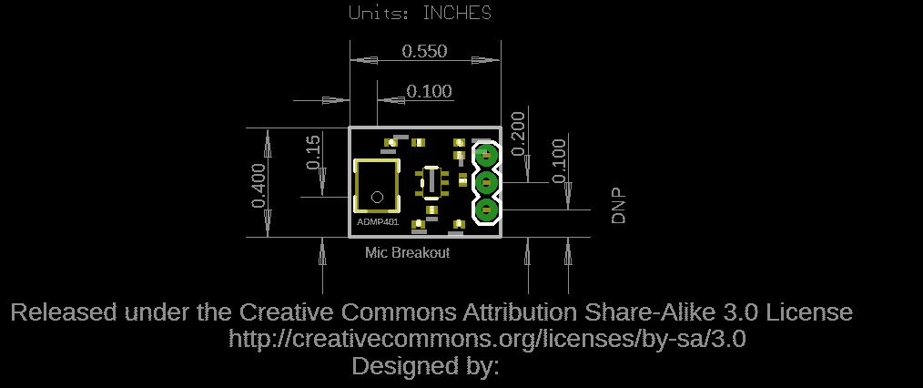
- -3dB roll off at 100Hz and 15kHz
- 1.5 to 3.3VDC supply voltage
- Should comfortably output 40mW
- SNR of -62dBA
SparkFun MEMS Microphone Breakout - INMP401 (ADMP401) Product Help and Resources
MEMS Microphone Hookup Guide
January 27, 2017
Get started with the SparkFun analog MEMS microphone breakout board with Arduino! Create a volume unit meter with the ADMP401 or ICS-40180 to react to sound before building your sound visualizer!
Bark Back Interactive Pet Monitor
March 8, 2017
Monitor and interact with pets through this dog bark detector project based on the Raspberry Pi!
Core Skill: Soldering
This skill defines how difficult the soldering is on a particular product. It might be a couple simple solder joints, or require special reflow tools.
Skill Level: Noob - Some basic soldering is required, but it is limited to a just a few pins, basic through-hole soldering, and couple (if any) polarized components. A basic soldering iron is all you should need.
See all skill levels
Core Skill: Electrical Prototyping
If it requires power, you need to know how much, what all the pins do, and how to hook it up. You may need to reference datasheets, schematics, and know the ins and outs of electronics.
Skill Level: Rookie - You may be required to know a bit more about the component, such as orientation, or how to hook it up, in addition to power requirements. You will need to understand polarized components.
See all skill levels
Comments
Looking for answers to technical questions?
We welcome your comments and suggestions below. However, if you are looking for solutions to technical questions please see our Technical Assistance page.
Customer Reviews
4.6 out of 5
Based on 11 ratings:
2 of 3 found this helpful:
Small but Mighty
Mems microphone breakout works great and is easily modified to change gain and filter characteristics. Very very small, but plenty of signal. Only suggestions are to 1) silkscreen or etch in copper connection legend (e.g. "+, G, OUT" on primary side (too), and 2) use a non-obsoleted part for the mems. The ADMP401 is obsolete, so moving forward, I'd have to use something else. Neither of these are a big deal, just suggestions on a future refresh. Overall, I LOVE this thing!
Fast delivery.
Good Supplier Highly recommended.
0 of 1 found this helpful:
I haven't had ime to try it yet
we monitor sea turtle nests here in Alabama. I want to see if I can bury it in the sand over the nest to hear when the eggs hatch and the hatchlings start to dig out. I assume it will need to be connected to an amplifier and loud speaker. Also D.C. power. If you have any suggestions, I would appreciate them. Thanks.
Extremely please with its performance ...
I used it in an arduino based sound level led project. I destroyed the first one when I used hot glue to mount it on the project. Glue covered up the hole and well ... that was it for that mems. I've had to get more creative in mounting it as it is small and does not have a mounting hole on the board.
It preforms extremely well and picks up the slightest sounds from across the room. Quit happy with the look and result.
fantastic
Much better than the electret microphone. Easy to use and doesn't pick up too much noise.
Have made a LOT of demo videos using this excellent microphone
I like to create sound reactive displays by using this microphone along with the FastLED display library. Most recently, I've recently updated my sound sampling routines to include squelch control, auto-levelling of the input signal, automatic gain control and more. It works great. Have also used it with basic sampling as well as a couple of FFT libraries. Just a great little microphone. Here's just one of many videos I've published using this microphone:
https://www.youtube.com/watch?v=zcw7_7pRLdY
Oh, and the code is all open source.
Very fast execution of order
The response time to send this device was 2 days. The device itself is more suited for my purposes than an adafruit competitor because the d.c. analog output is amplified, and sits at the mid Vcc point. Also there is no d.c. drift after power on.
ADMP401 MEMS Mic
Works very well, much better than condenser mics.
I've seen some comments/reviews that the ADMP401 is obsolete but my understanding is that this product line was sold by Analog Devices to InvenSense (hence the new code INMP401) and is not obsolete. https://www.invensense.com/wp-content/uploads/2015/02/INMP401.pdf
The amplifier design on this board is terrible at common mode rejection from the power supply. I have a 200mv 1Hz ripple on my battery powered application and it swamps out the amplifier and distorts the signal. The RC time constant of the resistor divider should be much larger than the input RC filter to reject common mode noise, and this design has it the other way round. See this guide.
I was pretty frustrated with this at first. I had the audio output tied directly to the ADC input and used an PWM-controlled LED to visualize the amplitude of the audio. It seemed that I had to tap on the microphone directly before I could see any change in the LED brightness, and even then sometimes it seemed to go the wrong way.
Then I hooked up my scope and it was a head-slapping moment. The signal is 1.5V +/- 1.5V. A quick (though maybe flawed) change to my code involved more or less rectifying the signal. I saved the midpoint value of the signal before monitoring the ADC value, then subtracted the current value from the midpoint value. The magnitude of the difference was then written to the PWM register. Now I can talk several feet away from the mic and it picks it up. :)
BTW, I clearly did not RTFM and I just hooked it up. If I had read the description, I would have known ahead of time that the mic sits at 1.5V.
seems like a lot of comments from people having issues, nearly didn't purchase... finally did, and happy to report no problems testing it out in a few minutes time.
soldered leads, hooked the VCC to the regulated 3V from my Arduino Nano, tied in GND, hooked the AUD output to an analog pin on the Arduino. then hooked 3 LED's to 3 digital outputs on the Arduino in order to create a little VU/SPL meter simulation:
with this code i can speak in a normal volume at 12"+ from the mic and light up the first led pretty solid and the second follows the volume peaks in my speech. if i move to within 6" of the mic or speak a little louder, the first & second LED's light consistently and the third peaks.
on these 5v Arduinos, i believe you could also use analogReference(EXTERNAL) with 3.3v to AREF in order to get more resolution: http://arduino.cc/en/Reference/AnalogReference - is that correct?
"on these 5v Arduinos, i believe you could also use analogReference(EXTERNAL) with 3.3v to AREF in order to get more resolution: http://arduino.cc/en/Reference/AnalogReference – is that correct?"
Yes, that is correct. I've recently used an Arduino Uno's 3.3V as an external analog reference while working with an CO2 sensor module.
Anyone had any luck connecting this to an Arduino? I'm using the 3.3V rail, and A0 as the input, and best case, yelling into it, I get maybe a 13-point offset from the nominal read of 300.
Hooking the audio output up to a scope, I see almost nothing unless I tap it on the table top.
Depending on which Arduino you have, try setting the analog reference to 2.5V or 1.1V. This will make the FULL SCALE analog input (i.e. 1023) to be 2.5 or 1.1 volts, giving you more "gain".
Note though that since you get a no signal offset voltage reading of 300 (which is 1.47 volts with a 5 volt reference), you will need to level shift the audio output signal if you use a 1.1 volt reference (because 1.47 volts is more than 1.1 volts and it would "peg" the analog reading at 1023).
This mic is very heat sensitive! You can easily kill it with a heat gun!!
I was making some voice-reactive jewelry with this little mic. My jewelry uses U-mold plastic; I use a heat gun to mold the plastic and add layers to the jewelry. Heating the plastic to make it playable resulted in the mems mic board not working. I did this twice before realizing what was happening. Please be aware!!!
If I put in backorder over 60 pcs , when can it be shipped?
That's a tricky questions. Please email cservice@sparkfun.com and they should be able to help you with that.
This mic works surprisingly well, but one word of warning: Do not connect the audio output pin to a low impedance load. My son was playing with the mic and tried to connect a small 8 ohm speaker directly to audio out and ground (with a +3.3V supply). The little op-amp on the board was killed by this. I don't know what the minimum recommended load impedance is, but probably to be safe send the signal to at least a 1K load or more.... maybe at least a 10K load.
Hi, I've connected this to a 3,5" jack then a headphones but I'm just earing some "scratch". I'm using a 3.2V 1000mAh battery, linked like this : Battery [-] : ** Gnd breakout and Gnd 3,5" jack / **Battery [+] : Vcc of the breakout 3,5" Jack [left] pin : AUD of the breakout. Maybe I can't use this like this ? thanks for your advice, G.
Is there a good way to make this somewhat less sensitive to moisture? I would need the microphone to be used in outdoor conditions. I plan to use heat-shrink cover, but as the moisture could seep in, I would prefer to varnish the circuit board as well. I tried spraying a silicon based varnish, but this makes destroys the microphone, especially when the vanish enters the small hole at the bottom of the breadboard. Would covering this small hole while spraying be a solutions? Or would you completely discourage any vanish all together?
Is there any chance of your doing a single or dual breakout board for the ADMP441? It is in the same family as the ADMP401 except it has I2S output which is kind of novel.
I'm using these successfully in a project, but now it seems the part is obsolete??
I was wondering what your process was for reflowing the Mems?
Somehow the PDF layouts have the correct pinning but the SparkFun Eagle library has the part backward. This would have been nice to know a few k$ in boards ago.
Is it possible to connect this directly to an preamplifier and record the audio output?
I get a very clear voice sound, but there is a constant high frequency noise. Then I connected the probe directly to the output of the ADMP401 MEMS device, bypassing the OPA334 OpAmp, and all the noise vanished. Any suggestions without bypassing it?
I'd be interested to connect the breakout board to a soundcard and power it with +48V phantom power.
Got this from the ding-n-dent (other).... I ordered 15x of that ding-n-dent.
I now have more mems mics than I will need in my life :O
An interesting project to do with the "broken" ie blow only sensors is to use a piezo speaker and make an altitude sensor. the principle here is to drive the piezo with a constant 3V p-p at around 2kHz then space the module a distance of a few cm. this should reliably detect altitude if also encased in a plastic tube with dessicant to keep out moisture.
Can someone send me some broken ones for analysis please? i think i know what went wrong. my opinion is that during soldering the fumes got into the tiny hole and gummed up the works. if so then this explains a lot...
i am on 4hv under "conundrum" :-)
well i went ahead and bought one. being speedy and trying to rush to finish my project, i applied 5v... and today reading this i scared myself, its a 3.3v device. but it works at 5v (not saying its safe) im going to go home and fix this asap. its no real change, its swaping the vcc and analog ref.
the day i got it i was already with some code from http://neuroelec.com/2011/03/fft-library-for-arduino/ and i wired it up and used http://code.google.com/p/serialchart/ to graph it, and it worked as expected.
than i modifyed the code to interface into the "Analog" RGB strips. and now i have a nice spectrum analizer. workes beautiful for music, going to play BlackOps and see how it looks. wrapped behind my tv.
I bought 5 pieces of this. Only 3 are working when I received them. Very high failure rate.
Want to buy this and feed it DIRECTLY to the ADC input of my PIC and capture audio (@10 KHz) onto the SD card on board. So what is the verdict?
All I see is people having difficulty in using this board.
Should I buy or not?
Thanks for your input.
Those aren't Eagle files.
You're right, they certainly aren't... in fact they appear to be Gerbers...
Fixed.
Hey guys,
I have a howto question...first time working with sound sensors. So kindly indulge my ignorance.
I have the ADMP401 hooked up to a machine tool (dont ask why..) via an Xbee module. I am powering the sensor and Xbee with a li-poly 3.7 V 1000 mAhr supply. The output is being read into Matlab. Did the same thing with the ADXL335 accelerometer before worked like a charm.
Now with the sound sensor, how am I to take the raw ADC'ed signal and convert to sound on matlab. In all, the reading that comes out is in mV, how do you go from mV to dB for this device so I can hear the machine 'talk' to me.
Thanks guys...
Sound sensors output signal which are bipolar and within a frequency range higher than many other sensors (100 Hz to 15 kHz for the ADMP401). If you want to use the microphone to report the global sound energy you must transform the microphone's raw signal into a unipolar and smoothed signal (usually this circuit is named an envelope follower). This signal would have a lower frequency range (below 100 Hz) and would suit better a transmission trough a serial port.
This part did not work as expected.
Used 3V power supply.
Measured AUD on oscilloscope.
The output was 1.5 V DC. No audio.
Tried a different power supply. Tried a different set of probes. Tried 3.3V Vcc. Never worked.
We tried another specimen and it worked until our tech soldered wires to the board so I think the reason that it did not work first is something which happens during soldering.
Sorry about that. Contact techsupport@sparkfun. You either have a bad board or something problematic with your setup. Either way, they'll get you taken care of.
Tis circuit seems to be inappropriate-it uses a relatively low impedance (1.5K) inverting amplifier, instead of the much higher 10K non-inverting configuration in the data sheet.
I's be interested to try it as a independant microphone (I mean not connected to Arduino or another board). How could I adapt it to a regular microphone +48V power ?
I looked at the specs for this mic at: http://www.analog.com/en/mems-sensors/microphones/admp401/products/product.html#similar_product_table....
It indicated a possible issue. This mic system has a VERY low current out 250 uA, into a VERY low 200 ohm impedance. That is NOT much juice. Use an Op-amp step up, or a FET amplifier? It's not working because there is nothing THERE!
This issue suggests that the op-amp OPA334 is not being driven at high enough gain. I replaced R4 100K (0603 size) the one closest to the AUD output pin, with a 1M 0603 resistor. Now the output level (P2P level) is much higher, ideal for input for Arduino or microcontroller. But not if you are using it to record audio.
I have tried to hook up this sensor to an Arduino Mega and I see almost no change in serial out put unless I blow in the microphone (still this only cause very little change in the output: a couple of quanta).
I noticed that other people have seen this problem. Is there any solutions? Problem with sensor? Problem with arduino? For me this seems to be a problem with the pre-amp...
Thanks in advance
toddkrein: Anyone had any luck connecting this to an Arduino? I'm using the 3.3V rail, and A0 as the input, and best case, yelling into it, I get *maybe* a 13-point offset from the nominal read of 300.
Hooking the audio output up to a scope, I see almost nothing unless I tap it on the table top.
i'm getting the same problem. Tried powering with 2.5v (2s rechargable nimh) and a 3v ldo and getting almost nothing on the scope. If i blow into the hole under the mems or hold my mouth right next to it, i can get a 100-200mv p/p signal, else nada.
SFE, have you had any other reports of this problem? Thx!
Still having issues? When I connect the sensor to analog in, power/ground using 3.3V on my Arduino Uno, I get a mean reading of 512 on the analog in pin, which is half of VCC. I have also confirmed this to work on a barebones breadboarded Atmega168V running the Arduino bootloader. <br />
<br />
I get pretty good spread from the mean reading - if I'm yelling into the thing, I get crazy jumps in the data, the amplitude jumps +/- 1.65V.
Did you manage to get it working?
The schematic link links to the datasheet.
Thanks for fixing the link.