- Home
- Product Categories
- Serial/UART
- SparkFun Serial Basic Breakout - CH340C and USB-C

SparkFun Serial Basic Breakout - CH340C and USB-C
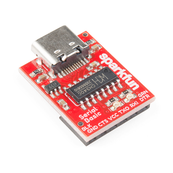
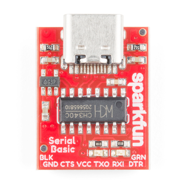
This SparkFun Serial Basic Breakout is an easy-to-use USB-to-Serial adapter based on the CH340C and takes advantage of the handy USB-C connector. With USB-C you can get up to three times the power delivery over the previous USB generation at 1.5A and and also solves the universally frustrating dilemma of plugging a USB cable in correctly, because it’s reversible! The Serial Basic works with 5V and 3.3V systems and possesses the capability to auto install on most operating systems without the need for additional drivers. The Serial Basic uses the CH340C IC to quickly and easily convert serial signals to USB.
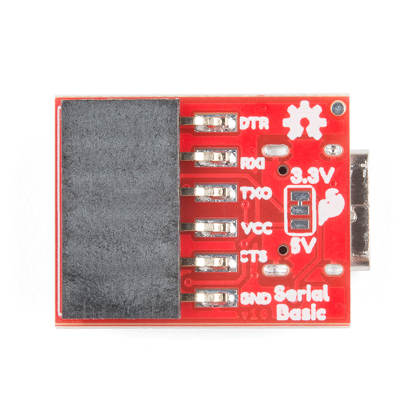
The pinout of the Serial Basic mimics the common DTR/RXI/TXO/VCC/CTS/GND pinout found on hundreds of FTDI-to-USB derivatives. It can also be used as a general serial device for debugging (such as with a GPS module). There is a jumper on the rear of the board that controls the output voltage on the VCC pin. By default, the board outputs 3.3V and has 3.3V signals. Changing this jumper to 5V will cause the board to output 5V on the VCC pin with 5V signals.
- Schematic
- Eagle Files
- Hookup Guide
- Fritzing Part
- Datasheet (CH340C)
- Drivers
- GitHub Hardware Repo
SparkFun Serial Basic Breakout - CH340C and USB-C Product Help and Resources
How to Install CH340 Drivers
August 6, 2019
How to install CH340 drivers (if you need them) on Windows, Mac OS X, and Linux.
SparkFun Edge Hookup Guide
September 26, 2019
Get to know your Edge board, including both the hardware features for you to utilize as well as how to get talking to it.
SparkFun Serial Basic CH340C Hookup Guide
December 13, 2018
SparkFun Serial Basic Breakout takes advantage of USB-C and is an easy-to-use USB-to-Serial adapter based on the CH340C IC from WCH. With USB-C you can get up to three times the power delivery over the previous USB generation and has the convenient feature of being reversable.
Core Skill: Electrical Prototyping
If it requires power, you need to know how much, what all the pins do, and how to hook it up. You may need to reference datasheets, schematics, and know the ins and outs of electronics.
Skill Level: Rookie - You may be required to know a bit more about the component, such as orientation, or how to hook it up, in addition to power requirements. You will need to understand polarized components.
See all skill levels
Comments
Looking for answers to technical questions?
We welcome your comments and suggestions below. However, if you are looking for solutions to technical questions please see our Technical Assistance page.
Customer Reviews
4.9 out of 5
Based on 8 ratings:
2 of 2 found this helpful:
Works well
This is my go-to for UART stuff. The voltage regulator can output 600mA at 3.3V, which saves me needing another power supply for most of my project.
2 of 2 found this helpful:
Perfect No Issues, Be Sure to Download Drivers
The power regulator is an AP2112 with "G3P" marking is rated for 600mA continuous, is this OK for 1.5A continuous? I was driving WiFi and some other stuff noticed it getting hot.
Super handy tool
Bought this to program an Arduino mini for an FM transmitter project. It was a perfect fit as the DTR line was available.
VJ340C with USB-C
I tried to interface the U-Blox F9P board from Sparkfun through the F9P's USB port, trying to bring the NMEA sentences back to serial communications into ports on an Arduino Due. Rigged VCC to the F9P board through the CH340C. No luck.
Good USB-C interface for my Teensy 3.x projects
This USB-C interface has the same pin out as the other USB interfaces providing me an easy peasy drop in USB port change for different users of my projects. It also allows me to use power from the connecting device or apply power via the USB for powering the connected device. It allows me to use either 3.3v or 5.0v as required too.
Send and receive text.
Needed a way to get text to a screen on a second channel and this did the the job. If it works what else can you say.
No problems using Ubuntu 18.04 and pyserial
I thought that there was a problem with the linux kernel driver, but after using python to talk to the ch340g from a ch340c determined that there was no problem. I was able to transmit and receive at 9600, 115200 and 921600.
Worked great the first time we tried it. Default was 3.3v and signals were correct polarity.
The V3 pin must be connected to 3.3V when 3.3V VCC is selected. When 5V VCC is used, it basically has a LDO built-in to step in down to 3.3V for it's USB logic to work.
Not sure if anyone noticed, but the LED resistors are not matched to the LEDs so the green LED is about half as bright as the yellow LED in operation. Would be nice if matched resistors were installed in the future.
Edit: maybe it's just the LED I have, both drop 1.8V, but the green one has an internal resistance of 1.3kOhm?
Can we get a SparkX version with the Red Squirrel 3V/5V Switch?
Excuse my ignorance, but what is the "Red Squirrel 3V/5V Switch"?
How much current can I pull from the 5V line? Is it as much as my Computer/Power brick will give me or is it somehow limited on board? I would like to use this for development but later on leave it on the board for Powering my project.
The board and USB-C in general, communicates it's "limit" with two resistors on the connector. This board is limited to 1.5 - 2A but is also limited by the trace width of the 5V line on the PCB. I can only safely recommend that you pull 1A, though I suspect you could pull a bit more. This could be a good question for the forums: forums.sparkfun.com, to pull on the experience of the SparkFun community.
I think I'm slightly confused. What's the difference between this and an FTDI Basic Breakout?
It is a serial device exactly the same as an FTDI, but with the difference being the chip on the product: a CH340C. It also uses a USB-C connector.
I really don't understand why sparkfun does not put a decent voltage selector like jumpers or a small switch on their serial breakouts. :(
Hello Vitor! If you look at the picture of the underside of the Serial Basic, it has a jumper for voltage selection (defaults to 3.3V).
yeah yeah, i know, but meant actually using jumper headers: https://www.sparkfun.com/products/9044 For example, this one is a really nice designed one with both a jumper selector to 5V and 3.3V AND disabling the power to the device. https://www.tindie.com/products/kdcircuits/ftdi-usb-serial-converter-5v33v/
if this only had a pin jumper instead of solder pads for the voltage selection it would be more useful than the visiport2.