- Home
- Product Categories
- 3-axis
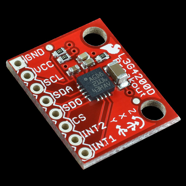
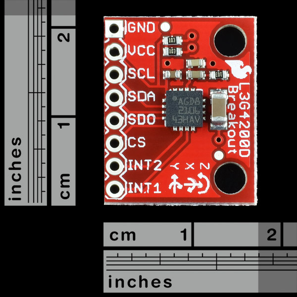
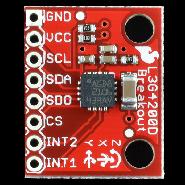
- SparkFun Tri-Axis Gyro Breakout - L3G4200D

SparkFun Tri-Axis Gyro Breakout - L3G4200D
This is a breakout board for the L3G4200D low-power three-axis angular rate sensor. The L3G4200D is a MEMS motion sensor and has a full scale of ±250/±500/±2000 dps and is capable of measuring rates with a user-selectable bandwidth. These work great in gaming and virtual reality input devices, GPS navigation systems and robotics.
Not sure which gyro is right for you? Our Accelerometer and Gyro Buying Guide might help!
- Three selectable full scales (250/500/2000 dps)
- I2C/SPI digital output interface
- 16 bit-rate value data output
- 8-bit temperature data output
- Wide supply voltage: 2.4 V to 3.6 V
- Low voltage-compatible IOs (1.8 V)
- Embedded power-down and sleep mode
- Embedded temperature sensor
- High shock survivability
- Schematic
- Eagle Files
- Datasheet (L3G4200D)
- Bildr Tutorial
- GitHub
SparkFun Tri-Axis Gyro Breakout - L3G4200D Product Help and Resources
Core Skill: Soldering
This skill defines how difficult the soldering is on a particular product. It might be a couple simple solder joints, or require special reflow tools.
Skill Level: Noob - Some basic soldering is required, but it is limited to a just a few pins, basic through-hole soldering, and couple (if any) polarized components. A basic soldering iron is all you should need.
See all skill levels
Core Skill: Programming
If a board needs code or communicates somehow, you're going to need to know how to program or interface with it. The programming skill is all about communication and code.
Skill Level: Competent - The toolchain for programming is a bit more complex and will examples may not be explicitly provided for you. You will be required to have a fundamental knowledge of programming and be required to provide your own code. You may need to modify existing libraries or code to work with your specific hardware. Sensor and hardware interfaces will be SPI or I2C.
See all skill levels
Core Skill: Electrical Prototyping
If it requires power, you need to know how much, what all the pins do, and how to hook it up. You may need to reference datasheets, schematics, and know the ins and outs of electronics.
Skill Level: Rookie - You may be required to know a bit more about the component, such as orientation, or how to hook it up, in addition to power requirements. You will need to understand polarized components.
See all skill levels
Comments
Looking for answers to technical questions?
We welcome your comments and suggestions below. However, if you are looking for solutions to technical questions please see our Technical Assistance page.
Customer Reviews
No reviews yet.
I think this product is a little overpriced, and this is why:
http://www.pololu.com/catalog/product/1272 it is the exact same thing, along with a bonus 3.3v regulator
Any body test the differece between L3G4200D and ITG3200?
Hi all. Sorry im a novice. Could someone advise if this could be used with any I/O board? I have purchased a digibee+ and since then have found this site. I have managed to hook digibee+ up to PC and can control it through Visual basic, but in terms of connecting something like this, to be quite honest, i dont know where to start. If anyone could recommend a good tutorial that would be appreciated.
Thanks in advance
We are having problems running the code given above. Accidently the 5V and GND were connected opposite for 3-4 seconds. There was no visible damage. How can we test if our device is still functional? Aren't there any inbuilt safety measures for such cases?
I just posted some code to the arduino forum which might be helpful. http://arduino.cc/forum/index.php/topic,147351.0.html
Jim
So this is what 'wide supply voltage' means now -- an entire VOLT of range! But not two volts. They didn't want to go nuts.
this is a bit expensive? The chip is only $12 in qty 1 and $6 if you buy 1000. I get SF has to make money but I see this being a $25 board not $50.
Also, the datasheet link needs to be updated. it doesn't have the register map, which makes this part quite hard to use. http://www.st.com/internet/com/TECHNICAL_RESOURCES/TECHNICAL_LITERATURE/DATASHEET/CD00265057.pdf
have you considered the fact that the board has to be designed, time has to be spent, its not just 12$ for the chip, it also price for design, for assembly, for soldring equipment, energy, + risk amount from failed parts, from the parts returned.
The datasheet says degree per seconds, but it seems to me that it's radiant per second. Can anyone confirm ?
The output values are scaled according to the sensitivity you select. At 250dps sensitivity, you must multiply by .00875 to get degrees per second.
I posted some code here that should help you: http://arduino.cc/forum/index.php/topic,147351.0.html
Link to decent datasheet: http://www.parallax.com/portals/0/downloads/docs/prod/sens/27911-GyroscopeAppNote2.pdf EDIT: actually, jstwinkles has got a better one above, my bad.
Please update the datasheet link. The one you have posted is super old and doesn't even have a register map.
Any chance of selling the sensor alone?
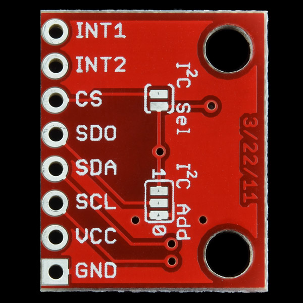
I think this device is intented to be a slave of a MCU, so, why put pull-up resistors in this board if probably the master can have it?
This sensor has a temperature sensor, but the datasheet nor the tutorials speak of it :( Any idea what the purpose of this is? More importantly, how do you read it?
The sheet available now shows OUT_TEMP at register 0x26, with a sensitivity of one bit change per degree C. It's probably used internally to keep the readings steady despite changing temperature.
The datasheet listed here is out of date, as of this posting. Here's a link to the latest version, which includes a register map and register descriptions: http://www.st.com/internet/com/TECHNICAL_RESOURCES/TECHNICAL_LITERATURE/DATASHEET/CD00265057.pdf
The datasheet listed here is out of date, as of this posting. Here's a link to the latest version, which includes a register map and register descriptions: http://www.st.com/internet/com/TECHNICAL_RESOURCES/TECHNICAL_LITERATURE/DATASHEET/CD00265057.pdf
If you are using this board in SPI mode be sure to take off the 10K pull up resistors from the SDA/SDI and SCL line. I had problems communicating with the device in their presence.
Hello,
I have adapted the example code to work with STM32-H103 and am doing the exact same thing as the example with different commands. However my SDO line is showing no output. I am operating it with MSBfirst in the correct modes and phase as per the datasheet @ 1.25MHz.
Am I missing something in the way it is initialized, or a trick in the way spi is setup thats causing it?
Is there any way to determine if the chip is functional?
Please refer the following link for the the
Oscilloscope images
Thanks in advance!!
I am also having the same problem getting this to work in SPI mode, SDO line does not seem to respond.
Hi there,
I am trying to get the gyro working (self assembled).
So I am not so sure if the program is buggy or the gyro ;-)
Can anyone check if this should return the who_am_I message?
http://www.my-shots.de/TEK0002.jpg
Anyone can explain me why all the 3 axis gyros have I2C/SPI outputs and not analog outputs? For my project I need simultaneous sampling of all the axis, otherwise I loose the orthogonality :S
Also, you might consider the ITG3200, which I believe does simultaneous sampling internally.
Tks for the advice! and the quick response :)
We tried. If we can find one we'll sell it. In the meantime, we still have a number of analog gyros, just no 3-axis ones.
A breakout-board with invensenses idg-500 AND isz-500 would be awesome!!!
does anyone know / have tested this device in a autopilot or as a quad stabilization unit? if so did it hold up well to the vibration?
Hi, missing datasheet link ??
Is there a datasheet out there with a register map?
I may be missing something obvious: output from this example code is in degrees per second, or is it in 10's of degrees per second?
And does that value change as you change the full scale selection? If you move from 250 dps to 2000 dps, is the output still in 10's of dps?
Sensitivity is described on page 10 of the datasheet. Output is generally digital counts relative to full scale. (signed 16-bit)
According to the data sheet, at 2000dps use a scale factor of 70x10-3 dps/digit which gives a range of +/-28572 , ie., a value of 285 is roughly 20dps.
Hello,
They give no information in the datasheet concerning vibrating frequency. Any hint ?
Regards,
Thomas.