- Home
- Product Categories
- Kits
- SparkFun Car Diagnostics Kit

SparkFun Car Diagnostics Kit
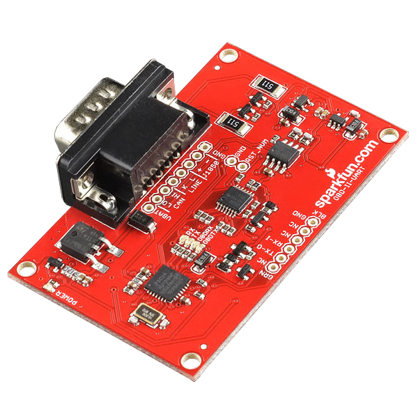
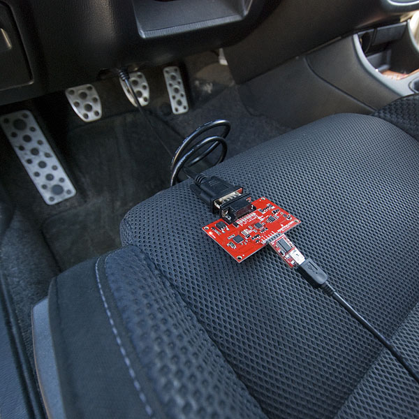
Has your "Check Engine Light" turned on in your car and you don't know what could possibly be wrong? We get it, it's a stressful situation that no one wants to be subjected to, and that's why we created the SparkFun Car Diagnostics Kit! The OBD-II included in this kit allows you to interface with your car's OBD-II bus. It provides you a serial interface using the ELM327 command set and supports all major OBD-II standards such as CAN and JBUS. The board also provides a footprint which mates directly to our FTDI Basic or a Bluetooth Mate. The DB9 connector mates with our DB9 to OBD-II cable listed below.
On-Board Diagnostics, Second Generation (OBD-II) is a set of standards for implementing a computer based system to control emissions from vehicles. It was first introduced in the United States in 1994, and became a requirement on all 1996 and newer US vehicles. Other countries, including Canada, parts of the European Union, Japan, Australia, and Brazil adopted similar legislation. A large portion of the modern vehicle fleet supports OBD-II or one of its regional flavors.
Among other things, OBD-II requires that each compliant vehicle be equipped with a standard diagnostic connector (DLC) and describes a standard way of communicating with the vehicle’s computer, also known as the ECU (Electronic Control Unit). A wealth of information can be obtained by tapping into the OBD bus, including the status of the malfunction indicator light (MIL), diagnostic trouble codes (DTCs), inspection and maintenance (I/M) information, freeze frames, VIN, hundreds of real-time parameters, and more.
STN1110 is an OBD to UART interpreter that can be used to convert messages between any of the OBD-II protocols currently in use, and UART. It is fully compatible with the de facto industry standard ELM327 command set. Based on a 16-bit processor core, the STN1110 offers more features and better performance than any other ELM327 compatible IC.
- Fully compatible with the ELM327 AT command set
- Extended ST command set
- UART interface (baud rates from 38 bps to 10 Mbps)
- Secure bootloader for easy firmware updates
- Support for all legislated OBD II protocols:
- ISO 15765-4 (CAN)
- ISO 14230-4 (Keyword Protocol 2000)
- ISO 9141-2 (Asian, European, Chrysler vehicles)
- SAE J1850 VPW (GM vehicles)
- SAE J1850 PWM (Ford vehicles)
- Support for non-legislated OBD protocols:
- ISO 15765
- ISO 11898 (raw CAN)
- Support for SAE J1939 OBD protocol
- Superior automatic protocol detection algorithm
- Large memory buffer
- Voltage input for battery monitoring
- Schematic
- Eagle Files
- Quickstart Guide
- Datasheet (STN1110)
- Datasheet (MCP2551)
- ELM327 Command Set
- Compatible Software List
- GitHub Repo
SparkFun Car Diagnostics Kit Product Help and Resources
Getting Started with OBD-II
October 8, 2015
A general guide to the OBD-II protocols used for communication in automotive and industrial applications.
Core Skill: Programming
If a board needs code or communicates somehow, you're going to need to know how to program or interface with it. The programming skill is all about communication and code.
Skill Level: Rookie - You will need a better fundamental understand of what code is, and how it works. You will be using beginner-level software and development tools like Arduino. You will be dealing directly with code, but numerous examples and libraries are available. Sensors or shields will communicate with serial or TTL.
See all skill levels
Core Skill: Electrical Prototyping
If it requires power, you need to know how much, what all the pins do, and how to hook it up. You may need to reference datasheets, schematics, and know the ins and outs of electronics.
Skill Level: Noob - You don't need to reference a datasheet, but you will need to know basic power requirements.
See all skill levels
Comments
Looking for answers to technical questions?
We welcome your comments and suggestions below. However, if you are looking for solutions to technical questions please see our Technical Assistance page.
Customer Reviews
3 out of 5
Based on 3 ratings:
1 of 2 found this helpful:
Need some schematic change
Greetings
i buy this product, and i read the hock up guide - and it was not working and i trouble shoot it. then i discover that both grounds from the RS232 and OBD2 headers aren't connected through the board. i use jumper wire between both and it works like a charm.
kindly, modify the hock-up guide.
Regards
Hi, sorry about this. I have your note in the hands of someone who can update that information. Happy hacking!
The hookup guide code didn't work
I purchased this thinking I could use this for a project. I followed the hookup guide verbatim, minus the fact that I used it on my Arduino Mega. The code doesn't work at all. I tried to cut out the lcd screen and just used the serial monitor to debug the code and nothing is working.
I send serial signals to the board and it never relays it to the vehicle. I've used it on 3 separate vehicles, none of them returned anything.In the sparkfun tutorial I find that the board gets stuck in the OBD getResponse function. I guess the Serial connection isn't available? I'm pretty sure the board is broken or something.
Hmmm, sounds like you need to contact our tech support team. They should be able to help determine the issue, and, if it's a borked board, get a replacement to you.
Can you use this to clear/reset codes?
Can this be used to send codes down to the vehicle or is it strictly read-only?
Incidentally, this "kit" is $10 cheaper than the microOBD-200 module sold by Scantool.net and has the same functionality, AND you get a cable with it, so call it $25 cheaper overall. Only major difference is the PCB size. ~1.5"x2.5" (for this product) vs. a 24pin .6" DIP (microOBD-200).
Can this be used to interface with Single Wire (swcan) on pin 1 of OBD II for GM cars? If so, it isn't clear how. The wire diagram of the cable also doesn't show how pin 1 on OBD II side of cable is connected, which is the swcan bus (for GM). I am having a heck of a time finding a decently priced solution for swcan bus usb adapter that speaks swcan.
You have several problems with the documents links. Schematic link is dead. The tutorial has several dead links to images. ELM327 Command set link is dead.
A major firmware update (v3.1.0) is available: http://www.scantool.net/downloads/updates/stn1110/
I made a similar board and wrote a simple python script to get RPM if anyone is interested. Schematics and layout are on github. https://github.com/nabilt/Bluetooth-ODB-2-Adapter/blob/master/scripts/obd.py