- Home
- Product Categories
- Kits
- SparkFun ClockIt

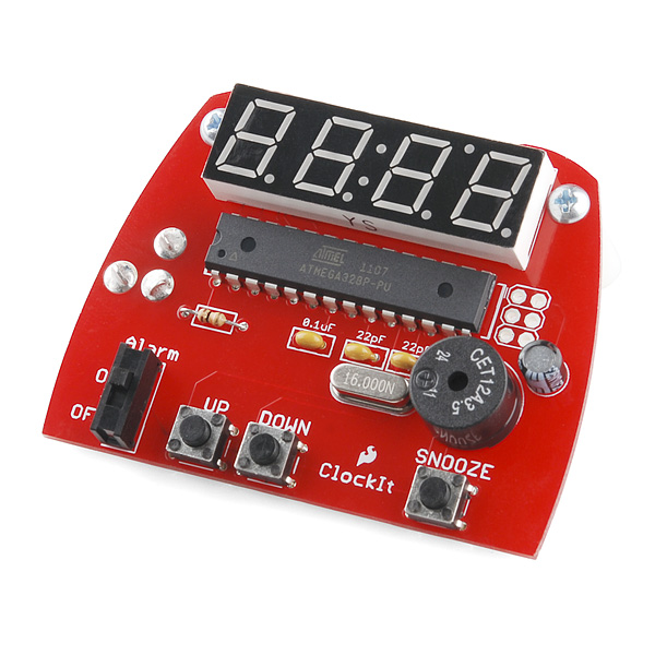
SparkFun ClockIt
This is a great kit to learn the basics of soldering. The SparkFun ClockIt is a basic alarm clock with buzzer based on the ever popular ATMega328. If you're just learning how to solder, this kit should take you 15-20 minutes. If you're a weathered pro at soldering, this is a great relaxing build that should take 5-10 minutes.
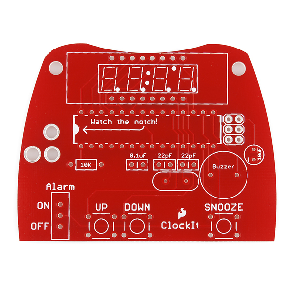
We've made some changes to this kit so it's easier for beginners to solder: The ATMega footprint is wider so you don't need to bend any pins and we've also added some more silkscreen print to better indicate the polarity of the parts.
No programmer required. The ATmega comes with firmware installed!
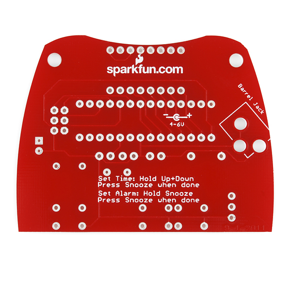
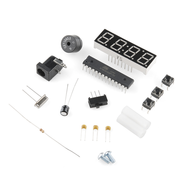
- 1 x ClockIt PCB
- 1 x ATmega328 (pre-programmed)
- 1 x 4-digit display
- 1 x Piezo Speaker
- 1 x 10uF cap
- 1 x 0.1uF cap
- 2 x 22pF caps
- 1 x 10k resistor
- 1 x 16MHz crystal
- 1 x barrel jack
- 1 x mini power switch
- 3 x push button reset switches
- 2 x Screws
- 2 x Plastic Standoffs
- 1 x 5V wall wart
- Time (AM/PM)
- Alarm (On/Off)
- Snooze (alarm resumes after a 9 minute snooze)
SparkFun ClockIt Product Help and Resources
Core Skill: Soldering
This skill defines how difficult the soldering is on a particular product. It might be a couple simple solder joints, or require special reflow tools.
Skill Level: Rookie - The number of pins increases, and you will have to determine polarity of components and some of the components might be a bit trickier or close together. You might need solder wick or flux.
See all skill levels
Core Skill: DIY
Whether it's for assembling a kit, hacking an enclosure, or creating your own parts; the DIY skill is all about knowing how to use tools and the techniques associated with them.
Skill Level: Noob - Basic assembly is required. You may need to provide your own basic tools like a screwdriver, hammer or scissors. Power tools or custom parts are not required. Instructions will be included and easy to follow. Sewing may be required, but only with included patterns.
See all skill levels
Core Skill: Electrical Prototyping
If it requires power, you need to know how much, what all the pins do, and how to hook it up. You may need to reference datasheets, schematics, and know the ins and outs of electronics.
Skill Level: Rookie - You may be required to know a bit more about the component, such as orientation, or how to hook it up, in addition to power requirements. You will need to understand polarized components.
See all skill levels
Comments
Looking for answers to technical questions?
We welcome your comments and suggestions below. However, if you are looking for solutions to technical questions please see our Technical Assistance page.
Customer Reviews
4.5 out of 5
Based on 4 ratings:
3 of 3 found this helpful:
Love It, great educational kit for my Scouts
Hi, I'm a Scoutmaster for a local Scout Troop. We bought a handful of these kits to help the boys learn to solder. What a great hands-on tool for them, they all did fairly well and learned much along the way.
Thanks for offering this kit at a reasonable price.
Great Beginning Kit
Not to many items, not to few. Perfect for someone like me who just started soldering. Very nice. Very basic. Works right after assembled, no programming necessary.
A practical project for improving your soldering skills
This project was soldered together in just a few hours with the addition of a socket for the ATMega328 MCU and headers for the display. I blogged about the build at http://ampubsvc.com/?p=188
A great Christmas Day activity for me and my boys.
I've three sons that I'd never gotten to take an interest in electronics hobbies. They've all become adults, but we all came together for Christmas this year. Each got this and the Simon Says kit.
We had an awesome time in my basement lab, with each of my "boys" building their first electronics project from scratch, and having them work - the first time!
Great stuff SparkFun, thanks for an amazing Christmas activity with my sons!
-------------------- Tech Support Tips/Troubleshooting/Common Issues --------------------
Common-Anode
This kit uses the 10mm common anode 7-segment display (blue) [ https://www.sparkfun.com/products/9481 ]. If you were to use this with a different color, make sure that you are using a common-anode 7-segment display.
Bigger 7-Segment Display
The absolute maximum ratings [pg 365 - www.atmel.com/Images/Atmel-42735-8-bit-AVR-Microcontroller-ATmega328-328P_Datasheet.pdf ] state that you can have only about 40mA per I/O pin and about 200mA through Vcc and GND. You will probably exceed these ratings if you are using a bigger 7-segment display. If you are using a bigger 7-segment display, you will probably need to use some transistors (i.e. BJT or MOSFET) due to the larger display's power requirements.
Here's one example using PNP transistors if you were using the 20mm 7-segments => [ https://www.sparkfun.com/products/11644 ]. Keep in mind that the example is using a common-cathode 7-segment display.
Modifying Code for Common-Cathode
You will need to modify the example code for common-cathode. You can probably use the older source code ( called clockit-v10.c ) from the older version [ https://www.sparkfun.com/products/retired/9205 or modify the clockit-v11.c for common-cathode. Since the example code was not Arduino based, you would need to generate the .hex file from the Makefile and an AVR programmer to flash the ATmega328P microcontroller if the 7-segment display was a common cathode.
I'm actually not very impressed with this kit. It was fun to put together, but the display is far too bright, the alarm is piercing (not unlike a smoke alarm), keeps very poor time, button debounce isn't great, and the crap PSU has an audible whine.
I bought two to make for my kids, nice project but seems quite overpriced for what you get. I realize some of this could be remedied by reflashing it, but it's supposed to be a beginners kit?
Fun Kit. My son (7th grade) and I built this over Christmas. He learned to solder and I learned to program AVR's. On the programing side there are a few things missing from the Source Code that need to be changed to get it working with the current hardware and latest (Dec 2013) WinAVR release. Also a few small bugs. I set up a GitHub repository with my modifications to the Sparkfun source code here: https://github.com/MarkDShattuck/Clockit. We also converted it to a stop watch (https://github.com/MarkDShattuck/Clockit-StopWatch). We plan to convert the hardware to take start/stop input from a laser/IR-receiver "trip line".
I know this is an extremely delayed response, but we now have a GitHub repo for this. We'd love a pull request to incorporate your changes :)
Just saw this. Would be happy to do a pull request, but I am new to GitHub and could not seems to do it. I have two entries that may be useful https://github.com/MarkDShattuck/Clockit and https://github.com/MarkDShattuck/Clockit-StopWatch. The Clockit-II there is not done. We gave the reprogramed clockit to my sons science teacher to use as a laser trip-line stopwatch for boats that the class builds and races, so I don't have it the kit around to play with anymore.
Have you tested accuracy? No RTC present... how much time does this clock typically gain/lose?
lots. I built this with my son a while back. It was losing/ gaining minutes a day when we gave up on it. You can do a pretty good job of keeping time if you have a decent crystal, keep the temperature fairly stable, and compensate for the given crystal's drift. I suspect either poor choice of crystals, or a bad batch of crystal's for my clock's poor performance.
The issue i found was in the software. In the interrupt routine, it resets the timer value for the next second.
You can fix it by deleting "TCNT1 = 49911;" from the ISR and changing the timer setup in ioinit() to this:
Bought the kit, loved it. Very cool build for a novice like me, excellent soldering practice. Crazy bright display though, and here's my saga of reprogramming to get it dimmer, and just to learn how. Keep in mind, N00b here... - Read the comments below - Bought a Pocket AVR Programmer - Installed the signed drivers for Win 8 - soldered a 3X2 pinout onto the Clockit - Figured out that the cable goes the other way when you hook the Programmer to the Clockit. The cable will lie across the IC when plugged in - Downloaded AVRDude - Downloaded AVR Studio - Set up AVR Studio to use AVR Dude and the Pocket Programmer, like here ( http://www.crash-bang.com/using-usbtiny-with-atmelstudio/ ) - Download the file above clockit-v11.c and open it in AVR Studio - Select-All-Copy the entire contents of the file and Paste into a new AVR Studio Project like here ( http://www.avr-tutorials.com/avr-studio-6/creating-new-avr-c-project-avr-studio-6 ) - Change lines 103 and 145 from ISR (SIG_OVERFLOW1) to ISR (TIMER1_OVF_vect) , like here, bottom of page ( https://forum.sparkfun.com/viewtopic.php?f=14&t=32059&p=142674&hilit=clockit+atmega328p#p142674 ) - Change the two instances of bright_level from 50 to 1 - Build the Hex file like here ( http://www.avr-tutorials.com/avr-studio-6/generating-hex-file-avr-studio-6) - In AVR Studio use the Pocket Programmer/AVRDude tool we set up above to flash the hex to the Clockit. - Find the display OK for a kids room or as a night light, but still too bright for my old eyes, so put 4 layers of TuckTape over the display also...
When I was young my parents bought me a heathkit alarm clock kit. I knew how to solder when I got that. but that was complicated. We never did get it working right. I think we had built up too much flux and crap (maybe a short) between the leads to the display.
Sure am glad it's not that complicated to make a clock anymore!
My daughter learned to solder with this clock. Super nice!
We want to re-program the clock to use it as a driver for a dimmer so we downloaded the source code above and loaded it onto a different ATMEGA328PU using our uno board. We then replaced the ATMEGA328PU that came with the clock with the one we downloaded the source code onto but the clock doesn't work -- all that happens is the buzzer is on continuously. Putting the original ATMEGA328PU back into the clock fixes the clock. Something is different between the ATMEGA328PU that came with the clock and the one we programmed with the source code.
Is this source code the correct version etc.?
I tried building another one of these by loading the code above onto a ATMEGA 328 (uno optiboot) that I placed in my R3 uno board. I used the same display and parts I actually had lying around from other projects. Built this on a breadboard per the above schematic (all sparkfun parts too...). When power is applied, the buzzer rings continuously, but nothing else happens. Verified wiring, several times times and it is wired per the schematic. Placed the same ATMEGA328 back in board and ran some other sketches on it and no issues. I'm too new at programming to pursue this further, but I had the same exact problem.
I am hoping someone can help me and my son fix the brightness (kid has to unplug it to go to sleep). We are novice (!) solderers and arduino programmers (generous description). I think I can figure out in the firmware how to adjust the brightness, maybe. But could someone spell out the specific steps to reprogram? What software do I need to compile and what type of connector do I need? Do I need a special programmer? Please assume you are talking to a someone slightly more intelligent than a monkey. My son LOVES (!) his clock he soldered, I would love to fix it for him. Thanks!
The firmware has the brightness code commented pretty well, that should be the easy part :)
For programming, you'll probably want to solder (not needed, but more reliable than smooshing it into place) some headers to the board at the ISP pads (the 3x2 unpopulated pads on the board), so that you can easily connect a programmer to it. There's lots of tools that will let you re-program the microcontroller (check the exact model through the labeling on top), but perhaps the easiest first step would be grabbing AVR Studio (Link is for AVR Studio 6, older versions are also available). See also the forums where there are some existing discussions about reprogramming a ClockIt :)
Thank you for taking the time to answer! I appreciate it. I will check out the links and see what I can do. I am sure it will be less time consuming than resetting the clock every morning!
It seems that ATMEGA168 was used instead of ATMEGA328PU!
If i can help, here's the pinout of the display : Commun anode 1 : pin 1 Commun anode 2 : pin 3 Commun anode 3 : pin 7 Commun anode 4 : pin 8
B = pin 4 A = pin 6 C = pin 11 F = pin 13 d = pin 14 g = pin 15 e = pin 16 . = pin 2
it seems that for the : , you have to put pin 5 to +5v and pin 12 to a 330 ohm resistor and then to ground, i didn't used the pin 2 for this project, i uploaded it into the ATMEGA168, so i didn't buy the kit! I didn't used the COL either.
I hope this helps! good night! marC:)
What is the 7 segment display used here ? what is the number id??
thank you! marC:)
This is a useful little kit not only as a clock but also as a generic display device. If only the designer had not used all of the analog input pins to drive the LED segments... this little kit could have made a nice custom panel meter (maybe to display voltage or current?).
One suggestion: This kit NEEDS a 28 pin 0.300 wide socket for the 328p chip. Radio Shack doesn't seem to carry 28 pin narrow sockets, but TWO 14 pin sockets in-line work just fine!
Here is a link to a photo of my board with two Radio Shack sockets installed: http://www.gunsnet.net/photopost/data/500/medium/clock-kit-socket.jpg
One last suggestion: This board should have a place to install an optional 3 terminal regulator (either through-hole or SMT) since it would be nice to use a 9v or 12v wall-wart instead of just 5 or 6 volts.
Otherwise, wonderful kit! It was loads of fun to assemble.
Just completed my clockit build which was easy to assemble and works great! But, i'm wondering is there any way to reduce the brightness of the display? At night my whole room illuminates blue.
The link to the schematic and assembly instructions does not work.
Should be up now! :)