- Home
- Product Categories
- Voltage
- SparkFun MOSFET Power Control Kit

SparkFun MOSFET Power Control Kit
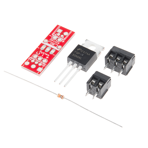
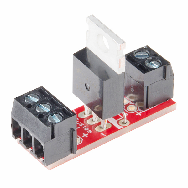
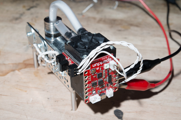
This is the SparkFun MOSFET Power Control Kit, a breakout PTH soldering kit for for the RFP30N06LE N-Channel MOSFET. This kit is extremely simple to assemble with only 10 pins to solder. If you are looking for a little more control over projects that require a little more power than normal but need a better way than your breadboard, this kit is perfect for you.
Included in each kit is a SparkFun MOSFET Power Control PCB, two screw terminals (one 2-pin and one 3-pin), a 10k resistor, and a single RFP30N06LE MOSFET. What we really like about this particular MOSFET is that it's very common and offers very low on-resistance with a control (gate) voltage that is compatible with any 3-5V microcontroller or mechanical switch. This allows you to control high-power devices with very low-power control mechanisms.
Note: While the MOSFET is rated to 60V 30A, the circuit board traces are only rated to 3.5A.
- 1x SparkFun MOSFET Power Control PCB
- 1x RFP30N06LE MOSFET
- 1x 2-pin screw terminal
- 1x 3-pin screw terminal
- 1x 10k resistor
- Schematic
- Eagle Files
- Datasheet (RFP30N06LE)
- GitHub (Design Files)
SparkFun MOSFET Power Control Kit Product Help and Resources
LED Light Bar Hookup
September 24, 2013
A quick overview of SparkFun's LED light bars, and some examples to show how to hook them up.
Non-Addressable RGB LED Strip Hookup Guide
February 19, 2020
Add color to your projects with non-addressable LED strips! These are perfect if you want to control and power the entire strip with one color for your props, car, fish tank, room, wall, or perhaps under cabinet lighting in your home.
Resources and Going Further
Feel free to look at this tutorial on the n-channel MOSFET as an example and for tips on using the transistor => http://bildr.org/2012/03/rfp30n06le-arduino/.
We also used this kit in a blog post on our web site. You can read about it here: Hardware Hump Day - Remote Smoke Machine Prank [ https://www.sparkfun.com/news/2344 ]
Using with a Motor
If you are using the MOSFET Power Control Kit with motors and solenoids, make sure to add a flyback diode between the motor and solenoid's terminal for protection similar to the schematic shown below:
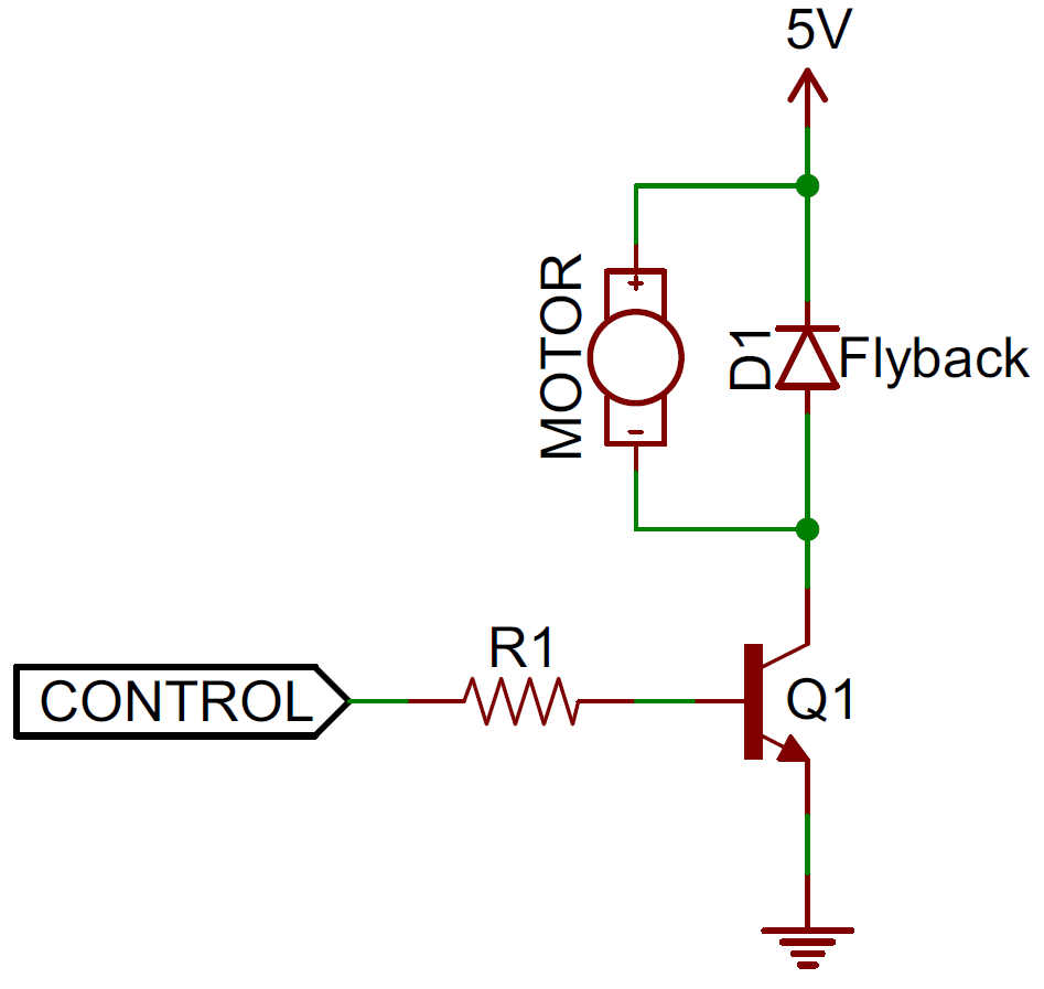
The example uses an NPN BJT but the circuit is similar if you were using the N-Channel MOSFET.
For more information about flyback diodes, check out our tutorial on Diodes: Diode Applications - Flyback Diodes and Voltage Spike Suppression. There are also two examples used in our old inventor's kit in circuit 12 and circuit 13. For a schematic, check out the inventor's kit manual on page 65 and 69.
1 of 1 found this helpful:
Hardware Hookup
The n-channel mosfet kit can be used to toggle a dc load when wired as a high-side load switch. As an example, we can use a microcontroller and one n-channel mosfet to toggle one color of the 12V non-addressable LED strip [ https://www.sparkfun.com/products/12023 ]. Below is an explanation of the pinouts and how to connect the system together:
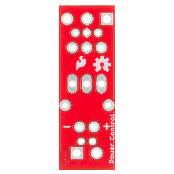
"System" Side
"C" = Gate, connect to microcontroller I/O
"-" = Source, for reference connect microcontroller's GND and the power source's GND
"+" = Vcc, connect to the "+" terminal of your power source
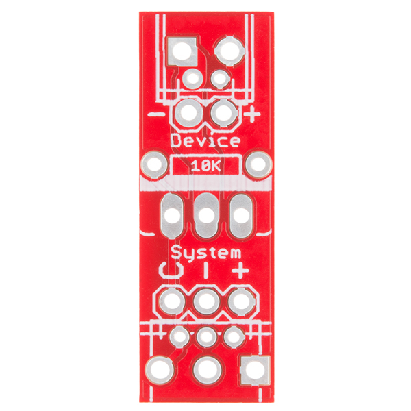
"Device" Side
"-" = Drain, connect this to "R", "G", or "B" cathode (-) of the 12V LED strip
"+" = 12V, connect to "12V" pin of the 12V LED Strip
We have a simple picture showing how to hook this up here with a DC load.
Core Skill: Soldering
This skill defines how difficult the soldering is on a particular product. It might be a couple simple solder joints, or require special reflow tools.
Skill Level: Noob - Some basic soldering is required, but it is limited to a just a few pins, basic through-hole soldering, and couple (if any) polarized components. A basic soldering iron is all you should need.
See all skill levels
Core Skill: DIY
Whether it's for assembling a kit, hacking an enclosure, or creating your own parts; the DIY skill is all about knowing how to use tools and the techniques associated with them.
Skill Level: Noob - Basic assembly is required. You may need to provide your own basic tools like a screwdriver, hammer or scissors. Power tools or custom parts are not required. Instructions will be included and easy to follow. Sewing may be required, but only with included patterns.
See all skill levels
Core Skill: Electrical Prototyping
If it requires power, you need to know how much, what all the pins do, and how to hook it up. You may need to reference datasheets, schematics, and know the ins and outs of electronics.
Skill Level: Competent - You will be required to reference a datasheet or schematic to know how to use a component. Your knowledge of a datasheet will only require basic features like power requirements, pinouts, or communications type. Also, you may need a power supply that?s greater than 12V or more than 1A worth of current.
See all skill levels
Comments
Looking for answers to technical questions?
We welcome your comments and suggestions below. However, if you are looking for solutions to technical questions please see our Technical Assistance page.
Customer Reviews
3.3 out of 5
Based on 18 ratings:
1 of 1 found this helpful:
Simple and does the job
Not much to this. Nice easy way to add a MOSFET to a project that doesn't otherwise need a board. Would be nice if it had a mounting hole on the board.
1 of 1 found this helpful:
Simpel and it works!
I am working with an raspberry pi 3 and have an actuator that needs 24 volts. And this circuit is perfect for this! so now i am controlling it with a 3.3 volts PWM an it converts it to 24 volts PWM.
1 of 1 found this helpful:
In the interest of hopeful criticism
The Mosfet Power Control Kit is fine except for its documentation. I soldered the product together and used my VOM to figure out where the traces went. I drew a simple schematic of what the "device" does and from there the inclusion in a project was easy.
I will email a drawing of the controller schematic for you to consider for your documentation upgrade.
Larry
4 of 4 found this helpful:
good luck understanding this little board
good luck wiring this without Eagle. The schematic makes some sense but doesn't correspond with the board markings... whats this RAW tag in eagle... what the heck does RAW mean..
I'd also have more landings for source as you at least always need to connect your control source and your high voltage source, right? Well assuming that you have two different voltages, say a 3.3 volt uController and a 12volt LED. That would make this a nice little board.
We use RAW to label power lines that have not passed through a voltage regulator, or to mark a variable voltage input into the system. There is usually a note designating the acceptable voltage range near the input on the schematic. In this case, the device can take a voltage up to 60V.
I'm sorry the connection steps were not clearer, this tutorial may help others in their hook up - http://bildr.org/2012/03/rfp30n06le-arduino/
3 of 3 found this helpful:
Only good for 3.5 amps
The MOSFET is rated for 60 volts, 30 amps.
The circuit board traces are rated only for 3.5 amps.
This information should be included in the description of the product.
It's misleading.
Sorry about the mix-up. We did have it listed in the schematic file under documents, but I can see how it would be misleading. We've added that as a note under the description. Thanks for raising that to our attention.
4 of 5 found this helpful:
Confusing!
In the end I had to buzz this out as I found the layout very confusing.
2 of 3 found this helpful:
Not quite perfect
Behind each screw terminal block, there are holes for 0.1" pitch headers. I thought these would work well for breadboard use. However, Sparkfun designed the board so that the 2-hole side falls directly in the gaps between the 3-hole side. This does not allow for smooth insertion into a breadboard. Also, the header rows are spaced just slightly off between the 2 rows so the breadboard wants to pull the headers apart. The board should be slightly tweaked to allow for use in a breadboard.
No way to mount it
Works as it should and easy to assemble. In practical use, there is no way to mount it to anything. End up having to pot it in a small plastic box.
Would be great if they made a single board with 4 of these that share a common Vin
0 of 1 found this helpful:
Deeply disappointed
I think the product is fine. For Heaven's sake... it OUGHT to be... not many simpler devices out there, are there? But I'm not sure. Out of time to hook it up, use it, now, after 4 hours to figure out.. I hope... what a diagram would have made clear in 20 seconds of my time.
But, despite YEARS of comments in these pages about the frustrations of figuring out how to hook it up... still no sensible "word" from Sparkfun. (The cited bildr page saved my sanity, I admit... but why did I have to dig in comments for it?? And it didn't help much with details of hookup, just reassured me that what I wasn't thinking wasn't madness.)
Took me 4 hours to figure out my guess as to how it ought to be hooked up. Mainly because a design, to me really SIMPLE, EASY, SENSIBLE, was NOT used. Instead, something I find messy and illogical.
I usually write up, publish, my answers, but at this stage I am so fed up, and so much time spent on this that I have little inclination, little time. If my guess is right, you need... unnecessarily... to stuff two wires (ground to Arduino/ ground of high voltage/current supply) into one of the terminal positions. And, on the 3 connector side, the Arduino "half" and the higher voltage/current "half" are "upside down" to one another. And ALL of the supplies of voltage are on one side (the three connection side), with the Arduino, and just the "supplied with high voltage/current" elements are on the other side. And don't forget the snubbing diode, if your load is inductive.
===
Another reason I'm not bothering to write this up is that I note that User 601528 says he sent a diagram 5 yrs ago, but don't see it on the Sparkfun page.
===
I think I see what the designer was thinking. There was a method to the madness. But "my" design is so simple, so obvious, and not, as far as I can see inferior in any way... and the complaints about confusion so common... that maybe someone at Sparkfun should have understood where the confusion was coming from, and dealt with it?
===
Had a bought a little kit from an eBay entrepreneur, at half the price, I wouldn't have been so bitter. But I pay the Sparkfun premium because usually that also buys me good documentation. And this was not, after all, so hard to document decently, and several people before me said they had had trouble, because of the lack.
Disappointed.
===
PS: NOW I see FURTHER discussion of the device in the "comments". Wish I'd seen that 4 hours ago. Wish the info was in the main part of this page. Not sure the comments really "answer" "how do you hook it up?". I have an answer now, I think, and have wasted enough time for now. The comments I glanced at weren't especially clear... except in repeating the refrain of "we need better guidance on this".
Incomprehensible
Probably my own stupidity, but I couldn't figure out how to work this break out board. Ended up going back to just a plain breadboard. I generally love Sparkfun but everyone once and a while they seem to drop the ball and this is an example. This board has been poorly reviewed, and they still haven't posted the documentation. The Eagle schematics don't seem to match what it actually is. Probably this could be solved by a single piece of documentation.
0 of 2 found this helpful:
Works as expected
The easiest way to dim LEDs!
Something so simple shouldn't be so complicated
Like others, I was frustrated trying to wire this up. But I was also frustrated by the people who said it took them 4 hours to figure it out, and then didn't take the time to post their solution.
So, here are a couple of the resources that helped me figure this board out:
1) https://forum.sparkfun.com/viewtopic.php?f=102&t=49679&p=203417&hilit=COM+12959#p203423
2) https://learn.sparkfun.com/tutorials/led-light-bar-hookup
quick solution
This is a good product to quickly control ~3A loads from a MCU
Very flexible and simple to use
I use these little boards to add LED lighting control to my Photon boards. I've experimented with using custom PCBs for my Photon based projects that incorporate this functionality, but each Photon board ends up controlling a different number LEDs. I've found that creating a generic PCB for the MCU, and attaching as many of these as needed works pretty well. These are super easy to assemble and connect, especially in my RV since lighting is all 12v anyways. I've never had a problem with these boards, and I'm currently using a couple dozen of them. I give it 4 stars instead of 5 because the output screw terminal is too small for the heavy gauge wire used in my RV. I can fix this though by using a larger screw terminal block that I purchase separately.
Just what I needed!
I'm building a homemade pinball machine and needed something to drive the solenoids(coils). These kits fit the bill, easy to assemble and work perfectly.
Documentation sucks
Parts showed up. No discussion of assembly. What the heck is "RAW"? What I learned was more about lack of end-user support than the application of the parts.
I'll press on, a few clues from this kit, but little help.
Yeah, thanks.
Sorry you're having trouble! The pictures on the product page above and the silk screen on the PCB should be helpful in determining where the parts need to be soldered. If you're still having trouble, check our Technical Assistance page for access to our tech support department and they can further assist you.
The two-port side is for the high-power device. The three-port side is for High Voltage (+), Common Ground (-), and Data (C)
So... how do I use this thing? Where do I hook up the microcontroller Vcc and where do I connect the high-power source? Is '-' on both sides actually Gnd? And I assume that the C connection goes to my PWM output?
Hi there, it sounds like you are looking for technical assistance. Please use the link in the banner above, to get started with posting a topic in our forums. Our technical support team will do their best to assist you.
Otherwise, please check out our LED bar hookup guide (also linked above in the tutorials section); it has a great example of how to use this kit with an Arduino based microcontroller.
So does this guy need a diode for inductive loads or is it built into the MOSFET? The data sheet seems to imply it may be built in.
hey good luck wiring this if you don't have EAGLE. The schematic makes some sense but it doesn't have corresponding markings with the PCB so it doesn't help you wire the mosfet.
I shorted the (+) and (-) source pin to make more landing spots for Source as the board seems pretty useless for my projects without this.
Is it me or the label behind the board is in the reverse. For the 3Pin connector from top, left to right you have "C" "-" "+", bu then in tutorials for examples https://learn.sparkfun.com/tutorials/led-light-bar-hookup/example-circuits they are connected as "+" "-" "C" . Label should be corrected I think.
EDIT: For this board the label is correct, the tutorial may be using other version.
Need HELP! How do i wire this kit? I have arduino connected to my motorcycle 12v. My purpose is to control 2 LED aux Lights (12v 20w each one) using PWM from Arduino. Should i connect the 2 wires from the battery to the 3 pin side of this kit, then connect from arduino 1 PWM wire + 1 GND to the 3 pin side, and on the 2 pin side the 2 wires follow to the Led Aux Lights. It is OK? Do you think i will need heatsink? (how big should i use?). Thank you very much.
Could this device be used to control a signal line? Specifically one from a USB source.
Can this guy control 48V motor?
Can someone explain the 10K resistor in this circuit? Does it provide ESD protection?
MOSFET gates are easily damaged when left floating because there is no circuit path for static discharge. (Other than through the thin gate insulation which would be bad). With a pull-down resistor on the gate you create another path. Also you ensure the MOSFET is in the off state when disconnected.
I love these little things but really wish they would come with an optional 1N4007 diode for flyback elimination when driving an inductive load.
Would it be okay to send about 10 A at about 12 V through one of these? I'm looking to build a BLDC motor control circuit and 10 A is the stall current of the motor.
The schematic says that the pcb traces only allow for 3.5 amps.
Survey says: Yes. Datasheet says 60 volts max drain, and 30 (!!!) amps continuous. (Power dissipation is 96 watts to +25 degrees centigrade.)
TBH: I'd have more concern over those screw terminals and the traces than the MOSFET itself. (Terminals are rated for 6 amps as 125 VAC.)
Actually the datasheet says "maybe". Looking at Figure 1 it looks like 10A at 12V is just slightly out of it's safe operating area for DC. If you're using a pulse width of 100ms or shorter you should be fine, but if you're using this as a switch to just turn the motor on you might have an issue especially if your environment is warmer than 25C. If I was going to give this a try I'd make sure to exceed the datasheet's recommended heat sink and/or use active cooling on it to give myself a better chance that it won't toast itself. Just my $.02
PS: 12V at 10A DC is 120W which is greater than it's 96W power dissipation.
Wouldn't that depend on where this 12 V actually is? If the MOSFET is turned on hard (say Vgs = 5V) Rds(on) will be about 0.047 ohms, at 1/20 of an ohm, 10A across the MOSFET is about 1/2V (the other 11.5V is across the motor) That would be around 5W for the MOSFET, one would want a heat sink, but otherwise it seems to me that would be ok. If one it trying to turn in on with 3V, I'd suggest one be generous with the heat sink with Vgs =3, Rds(on) may be 2 or 3 times as high as it is at 5V, if I'm interpreting figure 6 correctly.
Keep in mind that 10 A is the stall current, which will always be higher than the run current. Testing for a stall condition shouldn't be too hard (built-in reed switches). I used to have a link to the motors datasheet, but it quit working and I deleted it. The motor has three leads instead of four. I forget the configuration name, but it requires two leads to be used at a time: one tied to Vcc, one to Vdd, and one disconnected altogether. I would need six of these things to be able to run the motor and I was trying to determine what my best option is (mosfet switches or solid state relays or whatever else).