- Home
- Product Categories
- SparkFun
- SparkFun Block for Intel® Edison - PWM

SparkFun Block for Intel® Edison - PWM
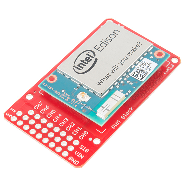
The Intel® Edison is an ultra small computing platform that will change the way you look at embedded electronics. Each Edison is packed with a huge amount of tech goodies into a tiny package while still providing the same robust strength of your go-to single board computer. Powered by the Intel® Atom™ SoC dual-core CPU and including an integrated WiFi, Bluetooth LE, and a 70-pin connector to attach a veritable slew of shield-like "Blocks" which can be stacked on top of each other. It's no wonder how this little guy is lowering the barrier of entry on the world of electronics!
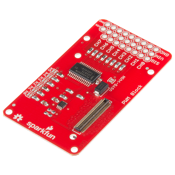
This Block adds eight channels of PWM control to the Edison's I2C bus. While the PWM output can be used for any generic PWM application, it is specifically intended to provide drive control for up to eight standard hobby-type servo motors. To that end, it has an independent input for supply voltage for the servos above the normal range of the Edison, and 8 connections that support the most common pinout of hobby servo motors. The PCA9685 equipped on this board has an independent clock that can be operated at 50Hz, for servo control; at that frequency, the 12-bit resolution of the device provides approximately 200 steps of resolution for a servo motor.
The PCA9685 can be used as an open collector current driver for LEDs up to 25mA as well. Six solder jumpers allow the user to attach up to 63 of these cards to a single Edison, or to adjust the address of the PCA9685 to avoid collision with other addresses on the bus.
If you are looking to add a little more stability to your Intel® Edison stack, check out this Hardware Pack. It will provide you with increased mechanical strength for stacking Blocks on your Edison!
Note: We are currently working on a Hookup Guide for this kit. Check back later for more updates.
SparkFun Block for Intel® Edison - PWM Product Help and Resources
General Guide to SparkFun Blocks for Intel® Edison
January 5, 2015
A general guide for using SparkFun Blocks for Intel® Edison in your next project!
Installing libmraa on Ubilinux for Edison
January 5, 2015
libmraa is a tool kit for interacting with various Intel single board computers.
Loading Debian (Ubilinux) on the Edison
December 5, 2014
How to load a Debian distribution (specifically Ubilinux) onto the Edison.
Programming the Intel® Edison: Beyond the Arduino IDE
January 7, 2015
Intel's Edison module goes beyond being just another Arduino clone. Check this tutorial for advice on how to get the most out of your Edison by writing code in C++!
SparkFun Blocks for Intel® Edison - PWM
June 22, 2015
A quick overview of the features of the PWM Block.
Edison Getting Started Guide
December 5, 2014
An introduction to the Intel® Edison. Then a quick walk through on interacting with the console, connecting to WiFi, and doing...stuff.
Core Skill: Robotics
This skill concerns mechanical and robotics knowledge. You may need to know how mechanical parts interact, how motors work, or how to use motor drivers and controllers.
Skill Level: Competent - You may need an understanding of servo motors and how to drive them. Additionally, you may need some fundamental understanding of motor controllers.
See all skill levels
Core Skill: Programming
If a board needs code or communicates somehow, you're going to need to know how to program or interface with it. The programming skill is all about communication and code.
Skill Level: Competent - The toolchain for programming is a bit more complex and will examples may not be explicitly provided for you. You will be required to have a fundamental knowledge of programming and be required to provide your own code. You may need to modify existing libraries or code to work with your specific hardware. Sensor and hardware interfaces will be SPI or I2C.
See all skill levels
Core Skill: Electrical Prototyping
If it requires power, you need to know how much, what all the pins do, and how to hook it up. You may need to reference datasheets, schematics, and know the ins and outs of electronics.
Skill Level: Rookie - You may be required to know a bit more about the component, such as orientation, or how to hook it up, in addition to power requirements. You will need to understand polarized components.
See all skill levels
Comments
Looking for answers to technical questions?
We welcome your comments and suggestions below. However, if you are looking for solutions to technical questions please see our Technical Assistance page.
Customer Reviews
No reviews yet.
I'm trying to use this in python... and I am a bit confused. So far I have just been using the FSYS Linux I2C Commands (i2cdetect,i2cget,i2cset) based on the i2c registers of the PCA9685. For example its address is 0x40 and the four byte registers for led0 are 0x06 for ON_L, 0x07 for ON_H, 0x08 for OFF_L, and 0x09 for OFF_H. I see that ON is the value from 0 to 4095 corresponding to when in the period the pulse starts, and OFF is the value from 0 to 4095 of the period when the pulse ends. I also see that this is a hex value, not a dec value, and that ON_L is the last two digits of the ON value in hex while ON_H is the first two digits of the ON hex value.
EX)
Turn on the pulse at 10% of the period and turn it off at 30% of the period so the signal is on a total of 20% of the period.
ON_time = (.10)*4096 -1=409 = 199h = 1h,99h=0x01,0x99=ON_H,ON_L
OFF_time = (.30)*4096 -1=1228 = 4CCh = 4h,CCh=0x04,0xCC=OFF_H,OFF_L
Yet this isn't working, though to my best knowledge this should work. I set the registers and that works. I read the registers and they are what I send them, but no LED light... Uising the GPIO Block I can set PWM and get the LED to turn on, but its 8 bit where this is 12 bit, so I like the resolution in this product.
Hopefully my board hasn't fried itself in all my attempts to get this working....
Anyway, I have also tried to write a program in Python based upon the C++ programs and looking at i2c MRAA examples in python, but so far no dice. I am sure at some point I can get this working, but progress is slow. If anyone has gotten this to work in Python, please throw me a bone!
Note: I am new to Python and Linux and hardware programming in general, so any advice is appreciated.
I have gotten the example in GITHUB compiled and working, but only by compiling it on the edison using make from the command line.
I cannot seem to get it to compile and download from eclipse.
Any help would be great.
There is an I2C voltage-level translator on this board it would be nice to have through holes to allow access to the outputs of this.
If the board is used with outputs configured for push pull then it is necessary to remove / disconnect the pull-up resistors to avoid unwanted power loss.
Also have to agree with request to change form factor. With a battery, I2C, microSD, base and PWM block this end of the stack of boards is getting very congested.
Fun little chip!
Folks using this will want to read the full datasheet
Make sure the two MODE pins are set correctly, and use 0xfa-0xfd to quickly test all outputs at once.
One thing to remember to keep in mind is how the board is going to stack with others once you've added .1" headers. May I humbly suggest that this board be reworked with the outputs along one of the longer edges of the board, because:
I'm having trouble getting the mraa's I2c module working, but the /usr/sbin/i2c* binaries work fine.
I've gotten some of i2c to work using mraa (not if i'm doing things correctly), maybe we should make a thread on the forums; share findings.
I made a post with all the stuff i've managed to get working (got it working). https://communities.intel.com/thread/63552
any updates on hookup guide for this?
is the Hookup Guide available?
Would it be possible to stack three of these on top of each other?
Yes, using the address jumpers it is possible to stack 32.
Can this board be used for reading PWM inputs? Or is the PCA9685 output only?
If there's only 4 PWM output, how can it control 8 servos using PWM?
How is this board programmed on the Edison? Either in the Arduino environment or in a native Linux environment.
can the edison be powered by soldering a correct +V jumper to the "vsys" pad before the diode? looking for a way to add power without a separate block.
is there an assembled option with breadboard pins?
will or can pins be supplied?
What is the PWM output voltage?
PWM output voltage is determined by VIN on the servo header.
nice job! another new board!
Does this allow for PWM in? Or just PWM out?
Out only.
Do you have a documentation package for the board some where?
We are waiting until details are finalized and production units are ready.
Any updates on this? Code samples etc?
https://github.com/intel-iot-devkit/mraa/blob/master/examples/python/bmp85.py Here's an example of communication with an I2C device in python.
bump