- Home
- Product Categories
- Registered Jacks
- RJ45 PoE MagJack

RJ45 PoE MagJack
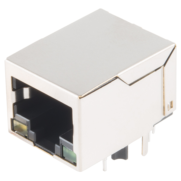
This is a very simple RJ45 PoEthernet MagJack connector that can help connect you to the Internet with the ability to provide power. Power over Ethernet, or PoE for short, is a system that’s designed to pass data and power, safely, over the same CAT5 cable. This specific connector was once used for our (now retired) SparkFun PoEthernet Shield. We found out we still had some left over stock and wanted to give you the opportunity to capitalize on the low price.
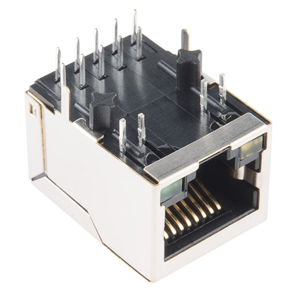
Inside each RJ45 are a number of transformers and magnetics required for isolating Ethernet signals. There are even some LEDs poking out the end.
Note: We are currently waiting on our supplier to get a Datasheet for the RJ45 PoEthernet MagJack. Check back soon for more information.
RJ45 PoE MagJack Product Help and Resources
Core Skill: Soldering
This skill defines how difficult the soldering is on a particular product. It might be a couple simple solder joints, or require special reflow tools.
Skill Level: Noob - Some basic soldering is required, but it is limited to a just a few pins, basic through-hole soldering, and couple (if any) polarized components. A basic soldering iron is all you should need.
See all skill levels
Comments
Looking for answers to technical questions?
We welcome your comments and suggestions below. However, if you are looking for solutions to technical questions please see our Technical Assistance page.
Customer Reviews
No reviews yet.
Zooming on the picture on the page of the PoE shield, we can read HanRun HY931147C on the magjack. Supposing it's the actual part, i've found a datasheet here: http://www.knap.at/datenblaetter/ste/ste_han_hy931147c.pdf
I'd be interested in buying some dozens if you could confirm it's really this part. Also searching for other PoE magjack models it appears there are some other with compatible pinout, sounds good news, as i'd like to have a reliable not too hard sourcing of parts for a current design i'll be extending and integrating into larger products.
-- UPDATE 2017-05-20: I've received 12 of those i've ordered, like in the picture on this page no marking on case, but i'm pretty confident they're actually HY931147C: Testing them with multimeter shows R(p2.p1)~=R(p2.p3)+R(p3.p1), same for p6.p4.p5, and a diode test on p9 and p10 shows no current one way, and 1.2V forward drop the other so it seems they also have the integrated diode bridges. Saving PCB estate of 2 DA4X106U0R or MB1S and associated traces :)
The datasheet doesn't mention max current for those diode bridges, so i'll sacrifice one for a max prolonged-load testing when i've returned to my lab and etched some breakouts (For those using KiCAD there is a footprint for this part in freetronics_kicad_library)
-- UPDATE 2017-05-22: Well, made 6 breakouts for those, and testing with some passive PoE injector i have the voltage present on P9 and P10, except the polarity is reversed compared to the HY931147C datasheet, i have + on P10 (outermost) pin and - on P9. To confirm the diode bridge is working well, i built a PoE injector with reversed polarity from an old RJ45 wall socket, at least the diode bridges are ok, as i still have +P10 and -P9. So either there's an error on the datasheet, or we have the nasty situation of 2 existing parts, one with no marking with exact same footprint but reversed polarity... will try to get somewhere one with the marking HY931147C to check if it's an error on the datasheet or really two different parts.
-- UPDATE 2017-11-03: Received a part marked HY931147C from another source, and confirms it has reversed polarity. Thought of adding a diode bridge but loses both neat integration and efficiency, so i'll keep using this one for my designs, and switch polarity on my future boards when this one no more in stock.
According to this website, the HY931147C does not have POE... Link: http://www.hqelec.com.cn/?product-6202.html
Maybe they had the wrong datasheet or part number and they've corrected between, but their current datasheet at: http://www.hqelec.com.cn/spec/hanrun/HY931147C.pdf is the same i had and clearly says "for 10/100Base-TX PoE application"
Well, i've finally completed the torture-test of this part for current-handling capacity, and it reveals itself very capable for its size. Results with arbitrary safe derating, before the TLDR details: 400mA continuous, up to 600mA vith thermal plane and/or some aiflow, peaks to ~1A for some seconds if it has time to cool down between, dies after 40min at 1.5A in open air.
The test setup:
A passive PoE injector powered by a 12V 6A power brick, a 20cm Cat5 patch cord to rule out cable losses, short wires soldered to the magjack power pins, green LED + 1kΩ resistor, and load resistors from KIT-13053, used in this order: 2 x 16Ω in series for 32Ω load, 2 x 8Ω series for 16Ω, 3 x 4Ω for 12Ω, 4 x 2Ω for 8Ω, 3 x 2Ω for 6Ω
Some caveats to keep in mind:
first measure voltage at jack output without load: 11V => 1V fV drop for the diode bridge unloaded
Then the actual tests, plugging the load resistors with:
Don't have an IR thermometer so just a vague appreciation of how hot it feels.
32Ω load:
16Ω load:
12Ω load:
8Ω load:
6Ω load:
Then, putting the Am-meter right between the power brick and the PoE injector shows no current (10mA, LED on the injector), so the diode bridge has failed open gracefully rather than short-circuit. Good news for people using dumb/passive PoE without current limiter (aka Fire over Ethernet protocol), though i would never rely solely on this over a proper current limiter or fuse.
Also, seems like part of plastic of the RJ45 connector of the cable melted inside the jack, as i can't anymore unplug it. Something to watch out, as you can't rely on simply unplugging (this end of) the cable as an emergency cut-off. (Even while still hot, pulling a melted still powered connector could likely cause a short, so always keep the other end of the cable, or better the power supply itself at reach for safety)
An interesting feature is the way the jack case heats, appears this part is doing a great job of using its metal case for dissipating heat away off the diode bridges.
To sum-up, i'd say it can safely be used up to the maximum of 802.3at PoE+ (Type 2) spec: 600mA on one pair of Cat5 cable, though above 350-400mA i'd recommend a PCB thermal plane and/or some airflow around the jack.
With a PoE+ voltage of 42 to 57V at powered device, depending on cable length and quality that still allows for a 25 to 34W load minus the switching reg losses.
Way more than enough for powering even a RasPi with loads of peripherals, and absolutely no thermal concern for my current uses: Omega2+ PoE dock and ATmega328+ENC28J60+HTU21D sensors PoE powered boards.
For those thinking of PoE type 3 and 4 (1.2 and 1.9A!), which uses all pairs for power, well, according to the datasheet there are actually two diode bridges inside, so the current would be spread across the two, but the failure timing and symptoms (after 40min continuous load) is clearly a case of thermal buildup rather than instant current overload, so that wouldn't help much more.
I doubt such current handling bridge could reasonably be implemented in something this compact and integrated (maybe using schottkys instead of PNs to reduce fV drop and thus dissipation?), all i've seen requiring this much power use external diode bridges (as those are obviously no more thumb-sized MCU+sensor boards)
But still very neat for miniaturization of low-power circuits and even powering very capable SBCs like RasPi.
Did anyone work out what the maximum current is that the internal diodes will pass on these without frying?
Done, i let you check my other post... happy PoE hacking :)
Can I use this with Intel Edison for power and wired network connectivity?
Any update on the datasheet? I want to buy these, but I need a datasheet to go with them.
Any word on the datasheet?
Does it support Gigabit?
Looking at the PoEthernet Shield schematic, I can see it only has pin-outs for two twisted pairs, so only 10/100.
Datasheet is coming in, but isn't that typically up to what's on the other end of the plug?
hi, any update about the datasheet? tks